Let’s be honest, you’re probably here because your dynamic mesh simulation just crashed. Again. That dreaded “Negative Cell Volume” error after hours of computation is a feeling I know all too well. When you’re dealing with large, complex motions—like a missile separating from an aircraft or a piston moving in a complex chamber—traditional remeshing methods often break down. They just can’t handle the topological changes without distorting the mesh into oblivion.
This is where a different approach, Overset Mesh, comes in. It’s a robust and elegant solution for these kinds of headaches. This technique is a cornerstone of what we cover in our deep dive into advanced CFD simulation techniques, and in this guide, I’m going to walk you through the practical steps and mindset needed for simulating complex moving geometries with overset mesh. We’ll move beyond the theory and get into the real-world workflow in Ansys Fluent.
What is Overset Mesh and Why Does It Outperform Dynamic Mesh in Certain Scenarios?
Think of Overset Mesh (sometimes called Chimera mesh) as a fundamentally different philosophy. Instead of one single mesh that has to stretch, squeeze, and rebuild itself constantly, you use multiple, independent meshes that overlap. There’s a primary, stationary “background” mesh, and one or more “component” meshes that move through it, carrying your moving objects.
The beauty of this is that each mesh can be optimized for its specific job. Your component mesh around the moving airfoil can be pristine and high-quality, and it stays that way because it isn’t deforming. The solver then intelligently figures out how to pass flow data between these overlapping mesh zones. It’s a powerfull tool that avoids the brute-force approach of remeshing entirely.
Overset vs. Traditional Dynamic Mesh: A CFDSource Comparison Table for Engineers
Choosing the right tool for the job is half the battle. I’ve seen projects delayed for weeks because the team insisted on using a dynamic mesh method that just wasn’t suited for large-amplitude motion. To make it clearer, here’s a quick comparison based on what we’ve seen in our projects:
| Feature | Dynamic Mesh (Remeshing/Smoothing) | Overset Mesh |
| Best For | Small displacements, deformations, boundary motion (e.g., oscillating flap). | Large, arbitrary, and unconstrained motion (e.g., store separation, ship maneuvering). |
| Mesh Quality | Can degrade significantly as motion progresses, often leading to divergence. | High-quality mesh is maintained on individual components throughout the simulation. |
| Setup Complexity | Can be simpler for basic motions but gets very complex to control for large movements. | Requires more initial setup (defining interfaces, cell types), but is more robust once configured. |
| Computational Cost | Remeshing step can be computationally very expensive at each time step. | Higher cell count due to overlap, but avoids costly remeshing algorithm. Can be faster overall. |
Core Concepts Explained: Background Mesh, Component Mesh, and Overlap Zone
Getting started with overset requires understanding its three key players:
- Background Mesh: This is your large, stationary domain. It’s typically a simple Cartesian mesh that covers the entire area where the action will happen. You don’t need it to be super fine everywhere; in fact, this is a great place to use techniques like efficiently using adaptive mesh refinement (AMR) to add resolution only where it’s needed.
- Component Mesh: This is the high-quality mesh that you create around your moving object(s). It moves with the object, like a custom-fit glove. All the critical physics, like the boundary layer, are captured here with a quality mesh that never changes.
- Overlap Zone: This is where the magic happens. 🤝 It’s the region where the component and background meshes physically overlap. The solver uses this zone to interpolate data and communicate between the grids, ensuring the fluid solution is continuous. Getting this right is critical.
Ideal Use Cases: When to Choose Overset for Your CFD Project
So, when do you pull the trigger on using Overset? It’s not for everything, but for some problems, it’s the only viable option. We’ve found it to be a lifesaver in these scenarios:
- Aerospace Store Separation: The classic example. Simulating a fuel tank or missile detaching from an aircraft wing.
- Marine & Offshore Applications: Modeling ship maneuvering, propeller-rudder interaction, or the motion of submersibles. I remember one project involving a ship propeller interacting with a rudder; the standard dynamic mesh just kept crashing because of the extreme proximity and rotation. Overset was the only method that gave us a stable, converged solution.
- In-Cylinder Simulations: The complex motion of valves and pistons inside an engine is a perfect fit.
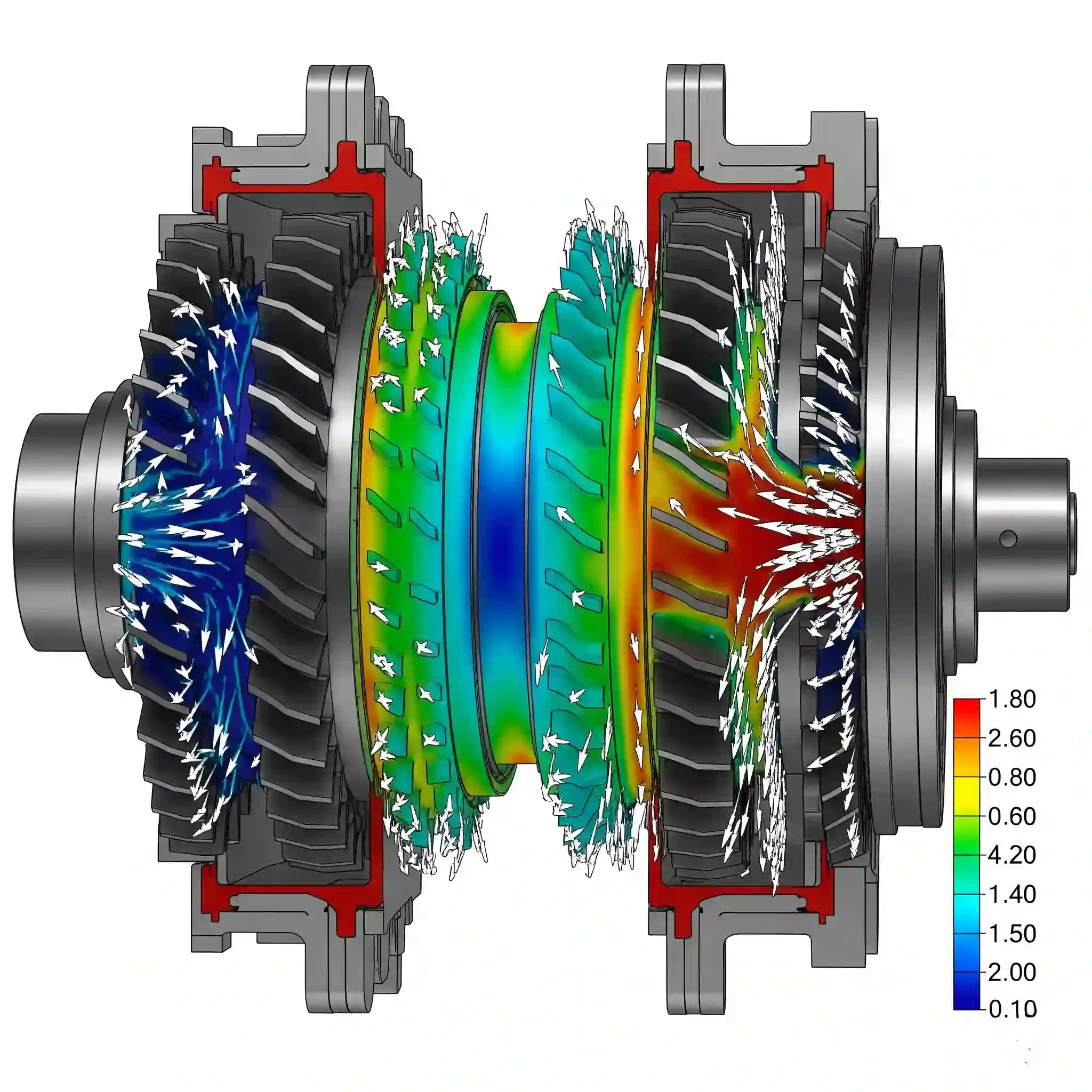
- Multi-body Interaction: Any scenario where multiple objects are moving independently or relative to each other, like gears or complex valve systems.
Handling these scenarios requires significant expertise, and the data generated from them is often business-critical. It’s a core part of our CFD analysis services to ensure these complex simulations are set up correctly and validated for industrial application.
The 5-Step Workflow for a Successful Overset Mesh Simulation in Ansys Fluent
Alright, let’s get into the weeds. This isn’t just about clicking buttons in the right order; it’s a workflow that requires foresight. Getting Step 1 wrong will cause a headache in Step 4. Think of it as a process, not a checklist.
- Geometry Prep & Boundary Definition: Isolate your moving parts and the stationary background domain. Crucially, you must define the surfaces that will form the boundary of the overlap zone as an overset boundary type.
- High-Quality Mesh Generation: Create your separate meshes. A structured, high-quality mesh for your component is non-negotiable. Don’t skimp here. The background mesh can be coarser, but must have enough resolution to capture the overlap.
- Interface Configuration: This is the big one. In Fluent, you’ll create the Overset Interface, pairing the background and component zones. This is where you tell the software how the different domains talk to each other.
- Motion Definition: How is your object moving? For simple, predefined paths, a profile file works fine. For motion that depends on the flow physics (like a valve opening based on pressure), you’ll almost certainly need to write and hook in custom code.
- Solver Setup & Post-Processing: Finally, you set your solver settings (PISO is often a good choice for these transient cases) and run the simulation. Make sure you know how to visualize the different cell types (active, inactive, etc.) to debug any issues.
Step 1: Geometry Preparation & Defining Overset Boundaries
Before you even think about meshing, get your geometry clean. The most common hiccup here is forgetting to properly name and designate the “Overset” boundary condition on the outer surface of your component domain. This boundary doesn’t act like a wall or an inlet; it’s just a flag that tells Fluent, “Hey, this is where the communication with another mesh happens.” Get this wrong, and the solver won’t even know you’re trying to perform an overset simulation.
Step 2: Generating High-Quality Background & Component Meshes
I can’t stress this enough: your component mesh must be excellent. Put your best boundary layer mesh on it, ensure low skewness, and treat it as if it were for a standalone simulation.
For the background mesh, the key is the cell size transition. There should be a smooth change in cell size between your component mesh and the background mesh in the overlap region. A rule of thumb is to keep the volume ratio between overlapping cells close to 1. A sudden jump from tiny cells on the component to huge cells in the background is a recipe for interpolation errors and divergence. 📉
Step 3: Configuring the Overset Interface: Your Key to Seamless Mesh Interaction
This is where you stitch everything together inside Fluent. When you create the Overset Interface, the solver performs a process called “hole cutting.” It identifies the cells in the background mesh that are covered by the component body and marks them as inactive. The cells just outside the component mesh become acceptor cells, which receive data from donor cells within the component mesh. If you see visual artifacts or convergence problems, your first debugging step should be to visualize these cell types and make sure the hole cutting looks clean and logical.
Step 4: Defining Motion with Profiles or User-Defined Functions (UDFs)
For simple, prescribed movements (e.g., constant rotation or linear velocity), using a motion profile is straightforward. But the real power of CFD comes from simulating physics-dependent motion. Imagine a wing flap that adjusts its angle based on the aerodynamic lift it generates. That’s not a simple profile.
For that level of complexity, you have to get your hands dirty with code. It involves writing your own logic to calculate forces and then update the mesh position at each time step. This is a topic in itself, and it’s why we emphasize the importance of extending Fluent’s capabilities with custom UDFs for advanced industrial problems.
Step 5: Solver Settings & Post-Processing for Accurate Visualization
With the setup complete, make sure you’re using a transient solver with appropriate time step size to capture the motion accurately. Second-order temporal discretization is usually required for good results. After the run, don’t just look at the flow contours. Use Fluent’s post-processing tools to display the overset mesh status. You need to visually confirm that the inactive, active, and donor/acceptor cells are behaving as you expect. This visual check is often the quickest way to spot a problem.
Troubleshooting Common Overset Mesh Errors: A CFDSource Field Guide
No complex simulation works perfectly the first time. Here are the issues that pop up most frequently.
The “Orphan Cells” Nightmare: How to Identify and Eliminate Them
An “orphan cell” is an acceptor cell in the background mesh that couldn’t find a valid donor cell in the component mesh. This creates a “hole” in your solution and will cause the simulation to fail. This usually happens when the background mesh is too coarse relative to the component mesh, or if the overlap region isn’t large enough. The fix? Either increase the overlap or refine the background mesh in the problem area. It’s a bit of an art to identfy and fix these efficiently.
Solving Convergence Issues Caused by Poor Data Interpolation
If your residuals are bouncing around and never converging, poor interpolation between the meshes is a likely suspect. Go back to Step 2. Is your cell size ratio between the overlapping meshes near 1? Is the quality of both meshes high at the interface? Fixing the core mesh quality is almost always the answer, rather than endlessly tweaking solver settings.
Best Practices for Balancing Computational Cost and Solution Accuracy
These simulations can be heavy. A key to managing this is automation, especially when you need to run multiple variations. You can’t afford to manually set up dozens of overset cases for a design study. Building a robust process from the start pays dividends. For complex parametric studies, we often find that automating the entire CFD workflow using Python scripting is not just a convenience, it’s a necessity to get the project done on schedule.
Proving the Power: A CFDSource Case Study in Aerospace Store Separation
We recently worked on a project simulating the release of a payload from a pylon under an aircraft wing. The initial attempts using dynamic remeshing failed repeatedly as the payload tumbled and moved unpredictably close to the wing. By switching to an Overset approach, we could maintain a perfect boundary layer mesh on both the wing and the payload independently. This allowed us to accurately capture the complex aerodynamic interactions during the separation event, and the predicted forces and moments matched the client’s experimental data with excellent fidelity. It simply wasn’t possible with the old methods.
Why Partner with CFDSource for Your Complex Motion Projects?
You can read the theory in the software manuals, but the real challenge is navigating the dozens of small decisions that make or break a simulation. When you’re comparing CFD analysis companies, look for the ones who talk about the problems, not just the features. The experience to anticipate and solve issues like orphan cells or interpolation errors is what delivers reliable results, not just colorful pictures.
Our Commitment to Validated Results and Confidentiality (NDA)
For our industrial clients, results are meaningless unless they are validated and trustworthy. We build validation steps into our workflow, comparing against empirical data or established benchmarks whenever possible. We also understand that your designs are your intellectual property. All projects are handled under strict non-disclosure agreements to ensure your data remains secure.
Final Thoughts On Your Overset Journey
Overset meshing is a truly powerful technique that opens the door to simulations that were once impossible. It has a steeper learning curve than standard CFD, but the payoff is the ability to tackle real-world, complex moving systems with confidence. Mastering the art of simulating complex moving geometries is a significant capability for any serious engineer or R&D team.
And once you’ve mastered capturing motion, the next logical step is to use that data to improve your design automatically. The simulation world is always moving forward, and it’s exciting to see things like how shape optimization with the Adjoint Solver is changing automated design and becoming more accessible.


