Why Your Radiation Model Choice Can Make or Break Your High-Temperature Simulation
Let’s be blunt. Picking the wrong radiation model is one of the fastest ways to get beautiful, colorful plots that are completely wrong. It can mean the difference between correctly predicting a critical hotspot in a gas turbine blade and missing it entirely, leading to catastrophic failure down the line. We’re talking about wasting weeks of computational time, only to realize your fundamental physics are flawed.
This isn’t just about academic accuracy; it’s about making sound engineering decisions. This guide cuts through the theory to give you a practical playbook. It’s a small part of a much bigger picture, which we cover in our guide on Advanced CFD: A Deep Dive into Modern Simulation Techniques. For now, let’s focus on getting radiation right.
First Principles: When is Radiation Modeling Non-Negotiable in CFD?
Before you even think about P1 or DO, ask yourself: do I even need this? The answer lies in the T⁴ term in the Stefan-Boltzmann law. Heat transfer from radiation scales with temperature to the fourth power. This means that as things get hot—really hot, think >500°C—radiation quickly stops being a minor effect and starts dominating convection and conduction.
If you’re simulating industrial furnaces, combustion chambers, glass manufacturing, or any process involving high-temperature gases and surfaces, ignoring radiation isn’t an option. It’s the primary way heat gets around in these systems. Forgetting it is like trying to model a river without accounting for gravity.
The 3 Core Radiation Models in CFD: A Practical Introduction
Most commercial CFD codes like Ansys Fluent or CFX will present you with a buffet of radiation models. It’s easy to get lost. But honestly, for 95% of industrial problems, your choice will boil down to one of three main players.
The P-1 Model: The Fast, First-Pass Approximation
Think of P-1 as your quick-and-dirty scout. It’s computationally cheap and easy to converge. It solves an extra transport equation for radiation intensity, treating it as a diffusion process. It’s main limitation? It assumes the medium is optically thick, meaning radiation doesn’t travel very far before being absorbed or scattered. It’s great for a first-pass analysis on something like molten glass, but it can be wildly inaccurate for optically thin or mixed media.
The Discrete Ordinates (DO) Model: The Accurate & Versatile Workhorse
This one is our go-to for most complex problems. DO solves the radiative transfer equation for a finite number of discrete solid angles, offering a great balance between accuracy and computational cost. It can handle both optically thin and thick media, and it’s brilliant for modeling participating media like flue gases in a combustion chamber.
I remember a project a few years back on a low-NOx burner. The initial P-1 simulation showed acceptable flame temperatures. But we knew something was off. Switching to the DO model cost us an extra day of meshing and setup, but the result was a 150°C higher peak flame temperature right where we suspected it, which completely changed our design approach. That experience really cemented how critical choosing the right radiation model in CFD is for us. The physics of these systems are often tightly coupled with other phenomena, not unlike the complexities involved in [simulating high-speed supersonic flows].
The Surface-to-Surface (S2S) Model: The Specialist for Non-Participating Media
What if the medium itself (like air at room temperature) doesn’t participate in radiation? That’s where S2S shines. It calculates the view factor between all the surfaces in your domain and ignores the fluid in between. This is perfect for applications like thermal modeling of satellites in a vacuum 🛰️ or analyzing heat shields where surfaces radiate to each other across a transparent gas. Using it for a combustion problem would be a mistake, but for the right application, it’s both accurate and efficient.
P1 vs. DO vs. S2S: A Head-to-Head Comparison Table by CFDSource
To make this even clearer, here’s a cheat sheet we’ve developed internally based on hundreds of projects.
| Feature | P-1 Model | Discrete Ordinates (DO) Model | Surface-to-Surface (S2S) Model |
| Accuracy | Low to Moderate | High | High (for its specific use case) |
| Computational Cost | Low | Moderate to High | Moderate (cost scales with number of surfaces) |
| Best For (Media) | Optically Thick (e.g., glass, furnaces) | All optical thicknesses, participating media | Non-participating media (e.g., air, vacuum) |
| CFDSource Pro-Tip | Great for initial runs to check for obvious flaws before switching to a more expensive model. | The default choice for combustion and complex thermal problems. Start with a coarse angular discretization (e.g., 2×2) and refine. | Don’t use it if you have participating media like soot or CO2. Your results will be wrong. |
Making the right selection from a table is one thing; implementing it correctly in a complex industrial project is another. It involves careful setup, meshing strategy, and result validation. This is precisely the kind of work our team handles daily through our CFD Analysis Services.
A Practical Decision Framework: How to Choose Your Radiation Model
Okay, theory is great, but let’s get practical. How do you decide? It’s not about which model is “best,” but which is “most appropriate” for your problem. You need to ask yourself a series of questions about your specific physics, because the requirements can be as different as those for [predicting cavitation in pumps] versus modeling a furnace. In the next sections, we’ll walk through specific industrial scenarios to build your decision-making muscle.
Scenario 1: Optically Thick Media (e.g., Industrial Furnaces, Boilers) – When to Start with P-1.
Are you working on a large industrial furnace or a molten glass tank? Here, the medium is often so dense with participating gases and soot that radiation can’t travel far before it’s re-absorbed. This is what we call “optically thick.” In these cases, the P-1 model is a perfectly reasonable, and computationally cheap, place to start. It treats radiation like a diffusion process, which is a fair approximation here.
However, even in a furnace, you might have localized regions near burners or openings that are optically thinner. P-1 can struggle there. Our usual workflow at CFDSource is to run a P-1 simulation first to get a feel for the overall temperature field, then use those results as an initial guess for a more robust DO simulation to refine the critical zones.
Scenario 2: Complex Physics & Participating Media (e.g., Combustion Chambers, Gas Turbines) – Why DO is Our Go-To Model at CFDSource.
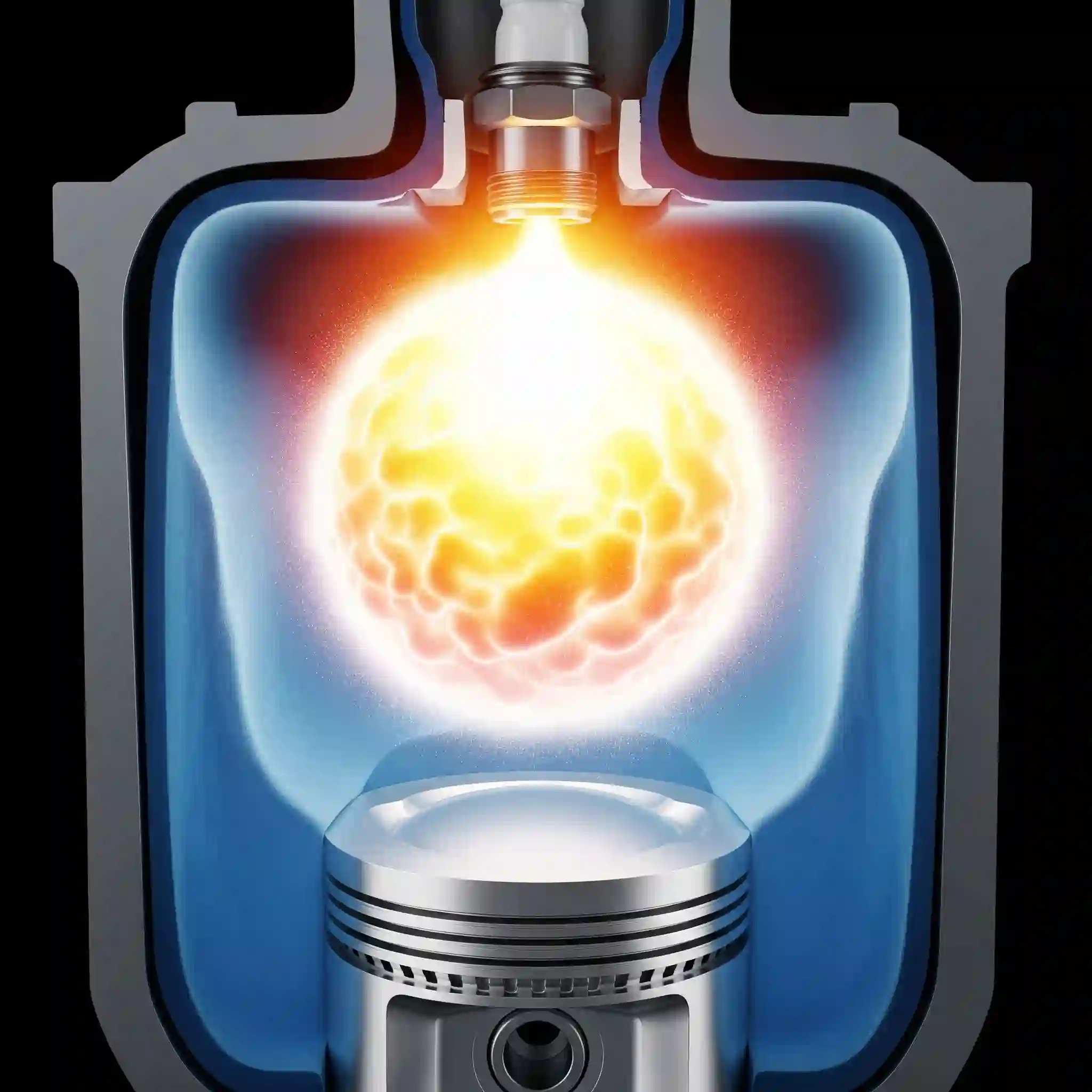
Now, let’s talk combustion. 🔥 This is a different beast entirely. You have a flame front, swirling gases, and crucial participating species like CO2, H2O, and soot, all with different radiative properties. The medium is a complex mix of optically thick and thin regions. This is DO territory, no question.
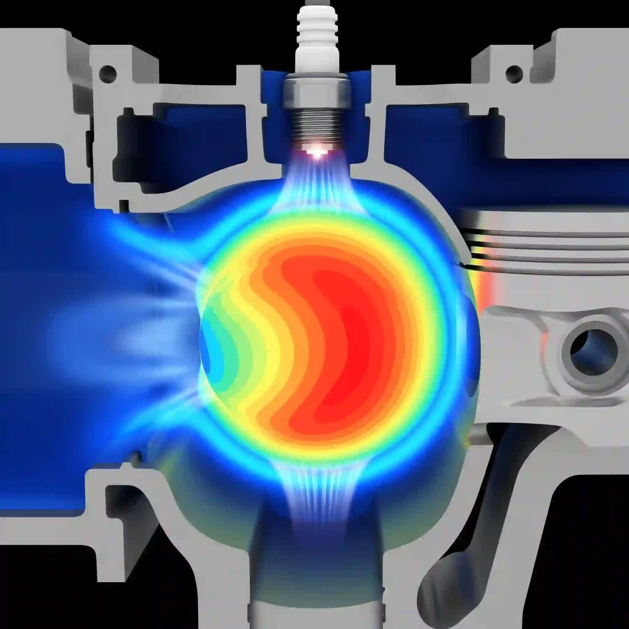
P-1 will simply not capture the highly directional nature of radiation from a flame to a combustor wall. DO, by solving the transport equation across multiple angles, gets this right. It’s more demanding, yes, but necessary. The physics can get extremely coupled, especially when you start considering things like [the complex physics of combustion noise], where pressure and heat release fluctuations interact. Getting the thermal field wrong throws everything else off.
Scenario 3: Non-Participating Media (e.g., Spacecraft Thermal Analysis, Electronics Cooling) – The Power of S2S.
What if the fluid itself doesn’t matter for radiation? Think of a powerful server rack where fans blow air over hot components. The air itself isn’t radiating much, but the surfaces of the CPUs and heat sinks certainly are radiating to each other and the casing. This is the perfect job for the Surface-to-Surface (S2S) model.
It calculates “view factors” between surfaces, essentially determining how well they can “see” each other. It’s computationally intensive if you have thousands of surfaces, but it’s incredibly accurate for this specific job. This becomes especially critical when these thermal loads cause parts to deform, leading to [coupled thermal-stress problems (FSI)] that can cause component failure.
Common Pitfalls & Pro-Tips from Our CFDSource Simulation Experts
You only learn this stuff by making mistakes. Here are a couple of hard-won lessons from the trenches.
The “Optical Thickness” Trap: A Common Misconception in P1 and DO.
This one gets everyone. People assume optical thickness is just about the physical size of the domain. It’s not. It’s the product of the absorption coefficient (alpha) and the path length (L). You can have a physically small domain that is optically very thick if it’s full of a highly absorptive medium like soot. Conversely, a huge domain of clean, hot air could be optically thin. Always check your material properties; don’t just guess based on geometry.
Setting Up in Ansys Fluent/CFX: Key Parameters You Can’t Ignore for Convergence.
A classic mistake I see junior engineers make is leaving the DO model’s discretisation settings on default. For a complex geometry, a 2×2 angular discretization is just too coarse and can lead to “false scattering,” where radiation unrealistically spreads out. Bumping this up to 4×4 or even 8×8 costs more compute time but drastically improves accuracy. Also, double-check your radiative properties at any wall boundry—getting the emissivity wrong can make your entire simulation useless.
Case Study: Validating the DO Model for an Industrial Gas Burner Project
We once worked with a client whose industrial burners were causing uneven heating in their process, leading to product defects. Their in-house simulations, using a simpler model, couldn’t explain it. The physics of the system were far from simple, completely different from our work [modeling non-Newtonian slurries] where viscous effects are king.
We rebuilt the model from scratch using the DO model, carefully defining the spectral properties of the combustion gases. The simulation revealed a large, cool recirculation zone that was being completely shielded from the flame’s radiation by its own swirling geometry. The older model missed this entirely. Our results guided a redesign of the burner’s swirl vanes, which solved the problem in their next prototype, saving them a fortune in wasted product. It was a perfect example of why a detailed radiation model was non-negotiable.
Need an Expert Review for Your High-Temperature Simulation? Partner with CFDSource.
As you can see, this gets deep, fast. The difference between a good and a bad simulation often lies in these nuanced decisions, which are based on experience. Sometimes you need more than just software; you need a sanity check from a team that has navigated these challenges for years. This focus on deep physical understanding is what separates experienced [CFD analysis companies] from the rest.
Ultimately, choosing the right radiation model in CFD isn’t just an academic exercise; it’s a critical engineering decision that directly impacts the safety, efficiency, and success of your design.


