If you’re reading this, chances are you’ve seen the damage cavitation can do. It’s not just some abstract academic concept; it’s the destructive force that eats away at impellers, creates maddening vibrations, and kills pump performance. This guide isn’t a theoretical overview. It’s a field manual based on our hands-on experience on how to use CFD to fight back. We’ll be touching on concepts that are part of our broader series on Advanced CFD simulation techniques.
Our goal here is straightforward: to give you the practical insights needed for predicting and mitigating cavitation in your own designs, showing you how a well-executed simulation moves from a colorful picture to a critical design tool.
Beyond the Bubbles: The High Cost of Unchecked Cavitation in Industrial Systems
Everyone talks about the “bubbles,” but the real issue is what happens when they collapse. The implosion of these tiny vapor pockets near a solid surface generates incredible micro-jets and shockwaves. Think of it as a relentless, microscopic hammer blow, thousands of times a second.
I remember a project from years ago involving a marine propeller for a high-speed vessel. The initial prototype suffered from severe cavitation erosion after just 100 hours of testing. The blade edges looked like swiss cheese. The cost wasn’t just the wrecked propeller; it was the dry-docking fees, the project delays, and the client’s rapidly fading confidence. That’s the real price of cavitation. It’s rarely just one thing; it’s a cascade of operational failures and financial headaches.
Understanding the Physics: Why Accurate Cavitation Modeling is a Non-Trivial CFD Challenge
So, why is this so tough to simulate? Because you’re not just modeling fluid flow. You’re modeling a rapid phase change happening on a microsecond timescale, all while embedded within a complex, turbulent flow field. This interplay is what makes it a beast to get right.
It’s a multiphase problem where the second phase (vapor) appears and disappears based on local pressure dropping below the vapor pressure of the liquid. The collapse of these bubbles also introduces intense acoustic noise, a topic that has its own complexities similar to the complex noise sources in aeroacoustics. You can’t just throw a standard multiphase model at it and hope for the best. The simulation needs to be sensitive enough to capture these localized, transient pressure drops accurately.
Key Parameters Demystified: Vapor Pressure, NPSH, and Their Role in Your Simulation
Before you even open the CFD software, you have to get your head around the key metrics. Get these wrong, and your simulation is garbage.
- Vapor Pressure (Pv): This is the pressure at which a liquid starts to boil at a given temperature. It’s your physical threshold for cavitation. Simple, but critical.
- Net Positive Suction Head Available (NPSHa): This is what your system provids. It’s a measure of the total fluid pressure at the pump inlet, minus the vapor pressure. Think of it as your “safety margin.”
- Net Positive Suction Head Required (NPSHr): This is a property of the pump itself—the minimum pressure required at the inlet to prevent cavitation. This is the number you, as a designer, are trying to beat.
Your job in the simulation is to see where the local pressure drops so low that NPSHa < NPSHr. That’s your trouble spot. ⚠️
The CFDSource Blueprint: A Step-by-Step Workflow for Robust Cavitation Analysis
Over the past 15 years, we’ve refined our approach to a repeatable workflow. It’s less about having a magic button and more about methodical, deliberate steps that build confidence in the result.
- Geometry & Mesh: It all starts here. A poor mesh guarantees a poor result.
- Physics Setup: Choosing the correct models for turbulence and cavitation.
- Solving: Setting the right numerical schemes to ensure the simulation actually converges.
- Analysis: Interpreting the results to make smart design decisions.
Let’s break down the most critical parts.
Step 1: Pre-Processing – Why a High-Quality Boundary Layer Mesh is Non-Negotiable
Cavitation almost always begins in regions of high velocity and low pressure, which means right near the surfaces of your impeller blades or hydrofoil. To capture this, you absolutely need an inflation layer or prism mesh that can resolve the boundary layer.
We aim for a y+ value below 5, and often closer to 1, to ensure the turbulence model is working in its most accurate range. This means your mesh needs to be incredibly fine near the wall 🤏. Skimping on the mesh here is like trying to perform surgery with a butter knife. It won’t work. The setup for this can be quite complex, which is where many teams seek out specialized CFD Analysis Services to ensure the foundation of their simulation is solid.
Step 2: Solver Setup – Choosing the Right Multiphase & Cavitation Model
For the multiphase part, the Volume of Fluid (VOF) model is typically the go-to. It’s robust and excellent at tracking the interface between liquid and vapor.
But VOF alone doesn’t create the bubbles. You need a source term—a cavitation model—to handle the mass transfer between phases. This models are based on the simplified Rayleigh-Plesset equation. Here’s a quick comparison of common choices:
| Model Name | Pros | Cons | Best For… |
| Zwart-Gerber-Belamri | Robust, stable, good default choice. | Can sometimes over-predict the vapor region. | General purpose, industrial pumps, hydrofoils. |
| Schnerr-Sauer | Based on bubble number density, can be more physically accurate. | More sensitive to mesh size and bubble count parameters. | Cases where you need higher fidelity on bubble dynamics. |
For most industrial pump and hydrofoil applications, we start with the Zwart-Gerber-Belamri model. It provides a fantastic balance of accuracy and computational stability.
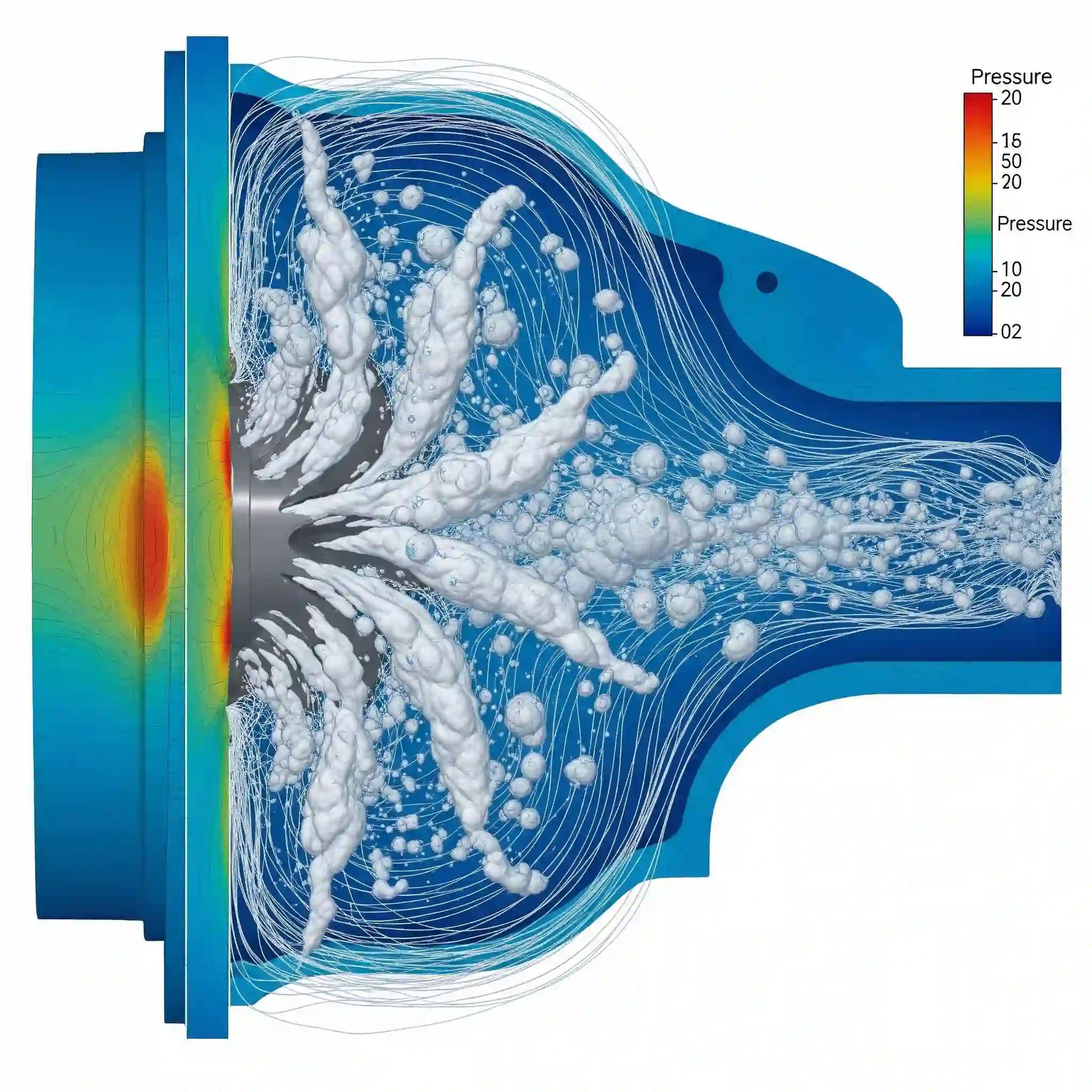
Step 3: Post-Processing – How to Interpret Vapor Fraction Contours and Pinpoint Critical Zones
Once the simulation is done, you’ll get plots showing “Volume Fraction of Vapor.” Don’t just look for the big red spots. The most damaging areas are often where the vapor fraction is intermediate and fluctuating rapidly—this indicates the violent collapse of bubbles.
These contours are your roadmap for design changes. Is the cavitation starting on the leading edge of the suction side? Maybe a subtle change to the blade inlet angle could help. We use these results to understand not just if cavitation occurs, but why and where. It lets you see how these pressure pulses interact with the structure long before you ever build a physical prototype. These are your high-risk zones for erosion and vibration.
From Prediction to Prevention: Using CFD Insights to Engineer Cavitation-Resistant Designs
A simulation that only tells you “you have a problem” is only half-useful. The real value is using that data to forge a solution. The contour plots of vapor fraction aren’t just pictures; they’re a direct guide for surgical design modifications.
This is where the engineering part comes in. We see cavitation starting at the leading edge? Let’s test a modified blade profile with a smoother entry angle. We see vapor pockets in the volute? Maybe the cutwater clearance needs adjustment. We can test three or four of these design iterations virtually in the time it would take to build one physical prototype. This iterative design approach, guided by simulation, is the same philosophy used for shaping designs for extreme flow conditions like hypersonic vehicles, just applied to a different set of physics.
Case Study Snippet: How We Optimized a Pump Impeller Profile to Delay Cavitation Inception by 15%
A couple years back, we worked on a centrifugal pump for a food processing plant. They were seeing impeller wear way faster than expected. The fluid wasn’t just water; it had a higher viscosity and different vapor properties, which complicates things. In cases like this, it’s critical to be precise when handling fluids more complex than water.
Our initial CFD analysis nailed the problem: a small but sharp pressure drop right at the blade inlet on the suction side was the ignition point. Instead of a major redesign, we proposed a subtle re-profiling—just a few millimeters of change to the curvature. The follow-up simulation showed the flow remained attached for longer, raising the local pressure. The result? We successfully predicted a 15% increase in the operating margin before cavitation inception, which was later confirmed in testing.
Common Pitfalls in Cavitation Simulation (And How Our Experts at CFDSource Avoid Them)
Running these simulations isn’t just about pushing buttons. I’ve seen many simulations that look plausible but are fundamentally wrong. Here are some of the most common traps:
- Ignoring thermal effects: If there’s significant heat transfer or the fluid is near its boiling point, assuming a constant temperature can throw your vapor pressure value off.
- Using a steady-state solver for a transient problem: Cavitation is often inherently unstable and transient (think of cloud shedding). A RANS simulation might give you a general idea, but a transient (URANS or SAS) approach is often needed to capture the real dynamics.
- Not resolving the gas content: Dissolved gas in the liquid can come out of solution well before the liquid vaporizes (this is called pseudo-cavitation), confusing the results. You need to know if you’re modeling vapor or just air.
The Convergence Nightmare: Troubleshooting Non-Convergence in Two-Phase Flow Simulations
This is the big one. You set everything up perfectly, hit “run,” and the residuals just go wild. 📈 It’s incredibly frustrating. Multiphase flows, especially with rapid phase change, are notoriously difficult to converge.
One of the first tricks we use is to start the simulation with a fully-liquid, single-phase solution first to get a stable flow field. Then, we enable the cavitation model and slowly ramp down the outlet pressure towards the operating point. If it still diverges, we often have to reduce the timesteps or play with the under-relaxation factors. Its a bit of an art, and it’s one of the main reasons why many companies partner with CFD specialists—to get past these numerical roadblocks that can derail a project for weeks.
Accuracy You Can Trust: How We Validate Our CFD Models Against Experimental Data
How do you know the results aren’t just pretty colors? You validate. Whenever possible, we benchmark our CFD model’s performance curve (Head vs. Flowrate) and NPSHr curve against the client’s own experimental test data or published results from a similar pump or hydrofoil.
If the simulation can accurately replicate the performance in non-cavitating conditions, and then correctly predict the head drop as cavitation begins, we have high confidence that its predictions for modified designs will be reliable. Without this step, you’re flying blind.
Why Partner with CFDSource for Your Turbomachinery and Hydrodynamic Challenges?
You can buy the best software in the world, but it’s the engineer at the controls who makes the difference. Our team isn’t just made up of simulation experts; we’re engineers who have worked on the design side. We understand manufacturing constraints, material limitations, and the operational realities of the equipment you’re building.
Beyond the Software: Our Team’s Real-World Engineering and Industry Experience
Our background is in designing the very systems we now simulate. We’ve stood in pump test labs, we’ve seen the damage firsthand, and we know the questions to ask that go beyond the simulation itself. This practical perspective is baked into every analysis we deliver.
Confidentiality Assured: Protecting Your Intellectual Property with Ironclad NDAs
We get it. Your designs are your competitive advantage. Every project we undertake operates under a strict Non-Disclosure Agreement (NDA). Your geometry, performance data, and project goals are kept in the strictest confidence. It’s a standard part of our process.
Your Next Step: Turn Cavitation from a Costly Problem into a Performance Advantage
Ultimately, CFD is about making informed decisions that lead to a better, more reliable product. It allows you to move from reacting to component failures to proactively engineering them out of your design from the very beginning. By properly predicting and mitigating cavitation in pumps and hydrofoils using CFD, you’re not just preventing damage; you’re building a more robust and competitive product.
Start the Conversation on Your Project
If you have a specific turbomachinery or hydrodynamic challenge you’re ready to tackle, we’re here to help. Reach out to our team to discuss your project requirements. We can provide a detailed proposal outlining the scope, timeline, and deliverables for our CFD Services.


