1. Why a Flawed CFD Setup Isn’t Just Wrong—It’s Expensive
Forget the fancy marketing talk. A bad CFD run can cost you more than just compute time; it can lead to a multi-million dollar product recall. I saw it happen once with a client designing a new electronic enclosure. Their in-house team missed a recirculation zone in a quick-and-dirty simulation. The result? A batch of 10,000 units that overheated and failed within months. That’s the reality of this field. It’s not just about getting pretty pictures.
Getting the fundamentals right is everything. If you’re just starting, you should really understand the basics of what CFD is and how it works, as it forms the foundation for everything we’re about to discuss. A solid setup doesn’t just give you a result; it gives you a reliable one.

2. Stage 1: Pre-Processing – Where 80% of CFD Success is Determined
People get excited about the solving phase—the big computers humming away. But ask anyone who’s been doing this for a while, and they’ll tell you the real magic, and the real headaches, happen in pre-processing. It’s meticulous, sometimes frustrating work, but if you rush this, you might as well be guessing. This is where you define the problem, clean up the geometry, and build the mesh that the solver will use. Get this right, and the rest often falls into place.
2.1. Geometry & Cleanup: The First Hurdle in Real-World Engineering Problems
The CAD models we get from design teams are rarely “CFD-ready.” They’re built for manufacturing, filled with tiny fillets, brand logos, and small gaps that are irrelevant to the fluid flow but will absolutely kill your mesh. ⚙️
Your first job is to play surgeon. You have to simplify and de-feature the model, removing anything that doesn’t impact the physics you’re interested in. Its not about changing the design, but about creating a clean, watertight volume that represents the fluid or solid domain. A classic example is removing the threads from a bolt hole. Do they matter for the overall airflow around the component? 99% of the time, no. But they’ll create millions of useless cells and ruin your mesh quality.
2.2. Meshing: More Than Just Shapes – Crafting a High-Fidelity Digital Twin
Meshing is the art of dicing your geometry into millions of small pieces, or “cells,” where the governing equations will be solved. A poor mesh is the number one cause of failed simulations. It’s not just about making the cells small; it’s about putting the right cells in the right places. For instance, in aerodynamics, you need extremely fine, layered cells near the surface of an airfoil (the boundary layer) to accurately capture drag. We obsess over metrics like Skewness and Orthogonal Quality.
This whole process of modeling is a key decision point when considering CFD analysis versus building physical prototypes. A well-crafted mesh is what makes your simulation a true digital twin. It’s the most critical part of the 3 core stages of a CFD simulation, and honestly, where most of the hands-on time goes.

A few things we always check before moving on:
- Mesh Quality Metrics: Is skewness below 0.85? Are there any negative volume cells?
- Boundary Layer Resolution: Have we captured the near-wall region correctly? For turbulence, we’re constantly checking the y+ value.
- Cell Count: Is it reasonable? You dont always need 20 million cells. Sometimes a smart 2 million cell mesh gives you a better result, faster.
2.3. Defining the Physics: How CFDSource Selects the Right Models for Your Industry
Once the mesh is ready, you tell the software how the fluid should behave. This is where you apply your engineering knowledge. Are you dealing with simple airflow, or is it a complex multiphase flow with boiling? Is heat transfer via radiation a factor? Each choice fundamentally changes the game.
You are essentially choosing which parts of the foundational Navier-Stokes equations to focus on and how to model phenomena we can’t resolve directly, like turbulence. This is where experience really pays off. Choosing the k-epsilon model when you should be using k-omega SST for a flow with strong boundary layer effects can lead to results that are off by 20-30%. For our clients, we provide comprehensive CFD analysis services that start with selecting the exact physical models needed for their specific application, whether it’s electronics cooling or simulating a chemical reactor.
Here’s a super simplified look at how we might choose a turbulence model:
| Turbulence Model | Best For… | CFDSource Note |
| k-epsilon (k-ε) | Fully developed, turbulent flows far from walls. (e.g., room ventilation) | Robust and fast, but not great for boundary layers. A workhorse for initial runs. |
| k-omega (k-ω) SST | External aerodynamics, flows with separation & reattachment. | Excellent for boundary layers and predicting separation. Our go-to for many aerospace and automotive jobs. |
| Reynolds Stress Model (RSM) | Complex 3D flows with high swirl (e.g., cyclones, combustors). | Computationally expensive but highly accurate for the right kind of problem. We use this when the others fail to capture the physics. |
3. Stage 2: Solving – The Computational Heart of Your Simulation
Okay, you’ve done the hard prep work. Now you hit “run.” This is where the computer takes over, iteratively solving those complex mathematical equations across every single cell in your mesh. It’s a process of converging towards a stable solution.
You watch the residuals drop (hopefully!), monitor key values like drag or pressure drop, and wait. 🤞 Depending on the complexity, this can take anywhere from a few hours on a workstation to weeks on a high-performance computing (HPC) cluster. This isn’t a “set it and forget it” step; we are constantly checking to make sure the solution is behaving physically and not just converging to a nonsensical answer.
3.1. Choosing the Right Solver: A Critical Decision (e.g., Fluent, CFX, OpenFOAM)
The software you use to solve the problem—the “solver”—matters. Each one has its strengths. Ansys Fluent might be fantastic for general-purpose aerodynamics, but for a complex rotating machinery problem, Ansys CFX could be a better fit. Then there’s OpenFOAM for those who need deep customization.
The point is, a true specialist doesn’t just use one tool; they choose the right tool for the job. This isn’t about brand loyalty; it’s about engineering efficiency and accuracy. We’ve seen projects stall because a team tried to force a problem into the wrong software package. It’s a costly mistake.
3.2. Convergence is Not the Goal, Accuracy Is: Monitoring Your Solution Like an Expert
Beginners get obsessed with the residual plot—those squiggly lines that go down. They think once the lines are flat, the job is done. That’s a huge misconception. Convergence just means the math is stable; it doesn’t mean the answer is physically correct. I’ve seen fully ‘converged’ solutions that showed a wing producing negative lift. 🤦♂️
The real work is monitoring key physical quantities. If you’re simulating flow over a car, you watch the drag coefficient. For a heat exchanger, you monitor the outlet temperature. You’re looking for these values to level off and become steady. That, combined with low residuals, tells you you’re approaching a trustworthy result. The final question of how accurate are these simulations anyway? is always tied to this careful monitoring process, not just a software message that says “Solution is converged.”
4. Stage 3: Post-Processing – Transforming Raw Data into Actionable Business Insights
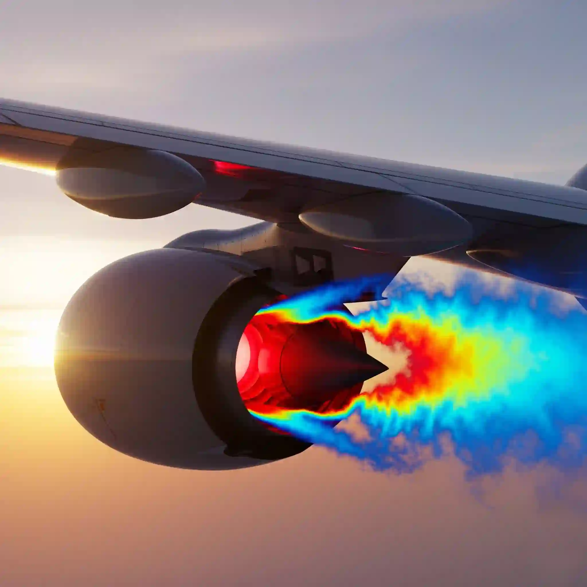
The simulation is done. You have gigabytes of raw data. So what? Post-processing is where you turn that data into answers. This is the stage where the true value of CFD is realized. It’s the difference between a pretty picture and a design decision that saves your company a million dollars.
This final step is where the entire effort pays off, providing the insights that drive innovation. You can see these principles in real-world CFD applications, from optimizing data centers to designing life-saving medical devices. The visuals are powerful, but the numbers are what drive engineering.
4.1. From Colorful Plots to Quantitative KPIs: Extracting What Truly Matters
Anyone can generate a velocity contour plot. It looks impressive. But a senior engineer or a manager will ask, “What’s the pressure drop in Pascals? What is the mass flow rate through port B? Is the peak temperature below the material’s limit?”
Post-processing is about extracting these key performance indicators (KPIs). We create charts, plots, and tables that directly answer the core engineering questions. We deliver reports that say, “Design A has 12% less drag than Design B,” not just “Here’s a picture of the airflow.” That’s the stuff that leads to better products.
4.2. The CFDSource Validation Protocol: How We Ensure Our Results Match Reality
How do you know the results aren’t just fantasy? Trust. You build it through validation. Whenever possible, we benchmark our simulation results against real-world data. This could be:
- Comparing our simulated lift and drag for an airfoil against historical wind tunnel data.
- Matching the pressure drop in a valve simulation with the manufacturer’s experimental data sheet.
- Validating our model against a trusted academic paper for a similar physics problem.
This step is non-negotiable for us. It’s our commitment to providing results you can confidently base critical design and investment decisions on.
5. Common Pitfalls That Can Derail Your Project (And How to Avoid Them)
After years in this game, you see the same mistakes pop up. Here are a few big ones:
- GIGO (Garbage In, Garbage Out): The most common issue. Incorrect boundary conditions, like setting a wrong inlet velocity or outlet pressure, will give you a beautifully converged, completely wrong answer.
- Ignoring Mesh Independence: How do you know you have enough cells? You need to run the simulation on a few different mesh densities to ensure the result isn’t changing significantly. Many people skip this to save time, and their results are often unreliable.
- Choosing the Wrong Turbulence Model: As we mentioned before, this is a classic. Using a simple model for a highly complex swirling flow is a recipe for disaster.
6. The CFDSource Advantage: How Our Streamlined Workflow Accelerates Your Time-to-Market
We don’t just run software; we manage a rigorous engineering process designed for reliability and speed. By focusing heavily on a clean pre-processing stage and continuous result monitoring, we eliminate the costly cycle of re-running failed simulations. This meticulous approach means we get to the right answer, faster.
Our structure is also built for flexibility. We leverage a network of specialized CFD freelancers and engineers, matching the specific physics of your project to an expert with direct experience in that niche. This ensures you’re not getting a generalist, you’re getting a specialist perfectly suited to you’re problem.
7. Ready to Transform Your Design Process?
Understanding the core stages of a CFD simulation is the first step towards leveraging its power. By treating it as a comprehensive engineering workflow rather than just a software task, you can unlock incredible insights, reduce physical prototyping, and get innovative products to market faster.
If your team is facing a complex fluid dynamics or heat transfer challenge, explore our case studies to see how we’ve solved similar problems. We’re here to help you navigate the entire process with confidence.


