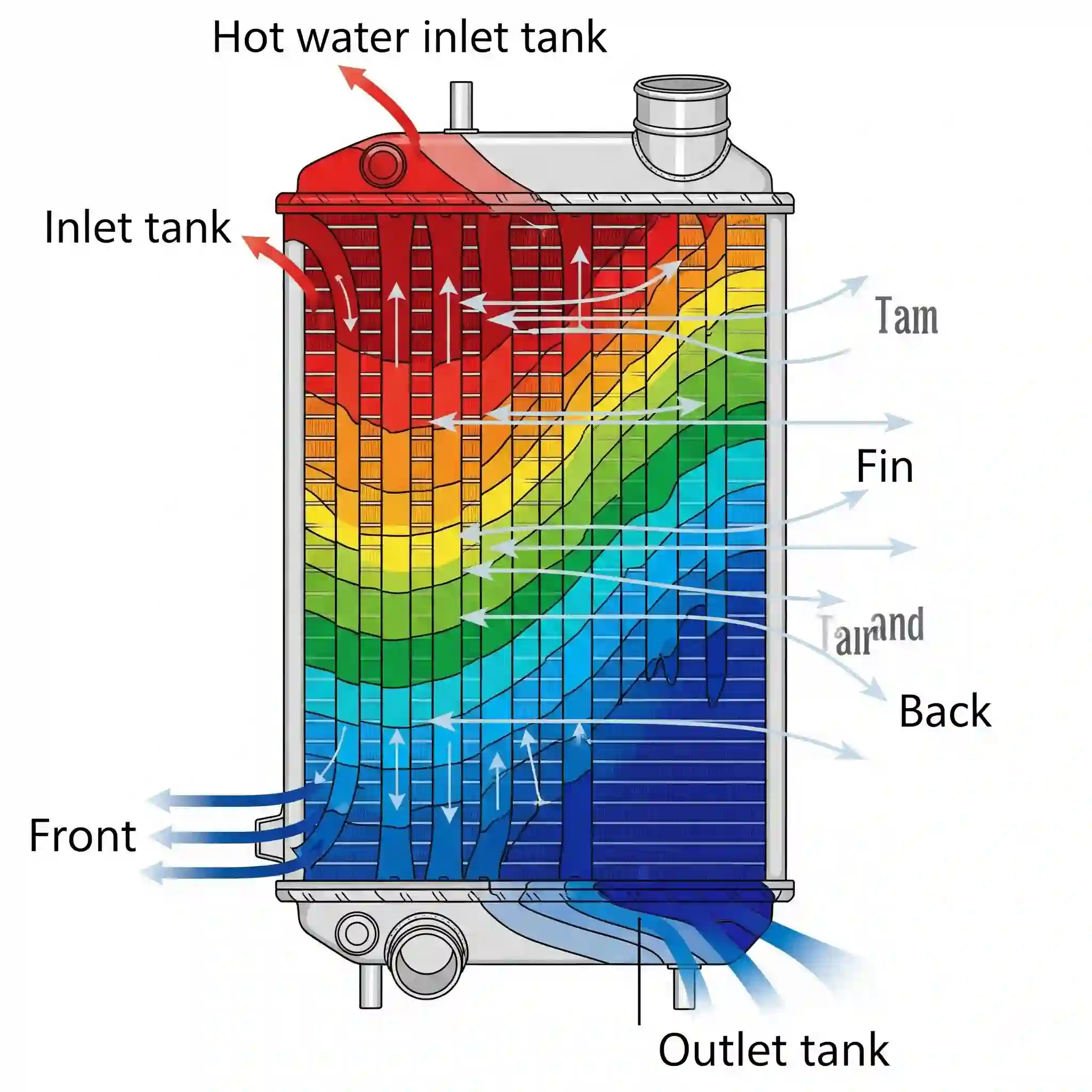
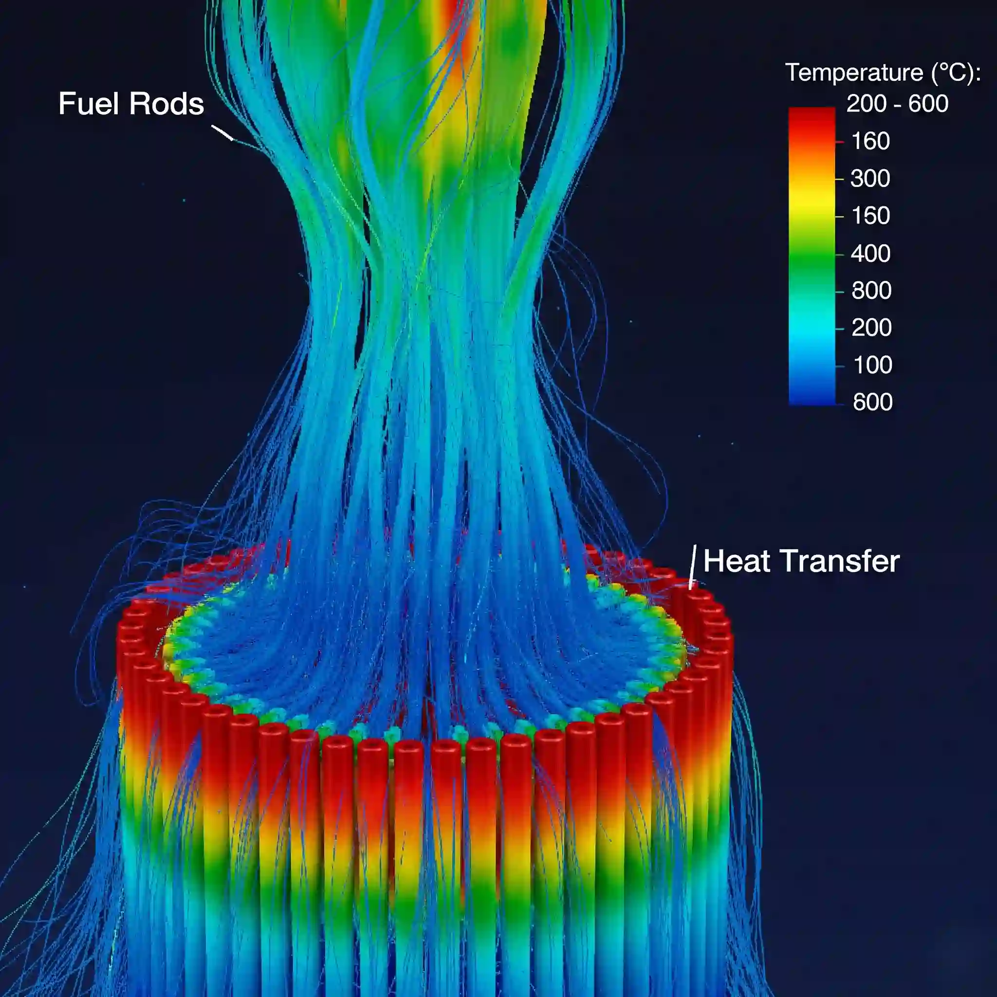
Ever stared at a thermal plot where a critical electronic component is glowing red, but the heatsink connected to it is a cool, comfortable blue? If the connection was perfect, that shouldn’t happen. That disconnect is where simplistic thermal models fall apart and where the real engineering begins. This is the world of Conjugate Heat Transfer (CHT), a discipline that doesn’t just look at the solid or the fluid, but the crucial dance between them.
Understanding this interaction is a cornerstone of modern advanced CFD techniques and is absolutely vital for accurate thermal design. This isn’t just about theory; we’re going to walk through the practical, hard-won lessons that make the difference between a simulation that looks pretty and one that actually prevents a product from melting.

Why Your Standard Thermal Analysis Is Not Enough: Understanding the Power of CHT
Look, it’s tempting to run a simple conduction analysis in an FEA package, guess a heat transfer coefficient (HTC) for the surfaces, and call it a day. We’ve all been there. But let’s be real: that HTC value you pulled from a textbook is an average, based on ideal conditions that probably don’t match your complex geometry. It doesn’t know about that little recirculation zone in the corner where air is barely moving, creating a massive hot spot.
A CHT analysis doesn’t guess. It calculates the heat transfer locally across every single surface element by solving the fluid flow and the solid conduction simultaneously. This is the only way to accurately capture the physics and find those unexpected problem areas before you build a prototype.
The Core Physics: Beyond Simple Conduction and Convection
The magic of CHT, and also its main challenge, happens right at that shared wall between the solid and fluid domains. The simulation isn’t solving two separate problems; it’s enforcing a physical law: the temperature and the heat flux on the fluid side of the wall must equal the temperature and heat flux on the solid side.
This energy coupling is continuous and dynamic. If a hot spot develops in the solid, the adjacent fluid heats up, its properties (like density and viscosity) change, the flow pattern shifts, and this in turn alters the cooling on the solid. This feedback loop is something a decoupled analysis could never capture.

Critical Industrial Applications: From Electronics Cooling to Engine Blocks
CHT isn’t some niche academic exercise. It’s the backbone of thermal management in countless high-stakes industries. We regularly see its application in:
- High-Power Electronics: Designing heatsinks, liquid cooling plates for CPUs/GPUs, and ensuring the thermal safety of dense server racks. 🖥️
- Automotive: Analyzing engine block cooling, exhaust manifolds, turbochargers, and battery thermal management in EVs.
- Aerospace: Turbine blade cooling, avionics thermal control, and analyzing aerodynamic heating on vehicle skins.
- Medical Devices: Simulating heat distribution in tools for radiofrequency ablation or ensuring implants don’t overheat.
Getting these analyses right requires a deep understanding of both the physics and the software. It’s the kind of work that defines high-quality CFD analysis services.
Setting Up for Success: The Non-Negotiable Pre-Processing Steps for CHT
After more than 15 years in this field, I can tell you that 90% of CHT simulation failures happen before you even open the solver. “Garbage in, garbage out” has never been more true. I remember a heat exchanger project early in my career; we spent a week trying to get it to converge, only to find a tiny, sliver surface in the CAD that was wrecking the interface mesh. A rookie mistake, but one that cost us days. It taught me that pre-processing is not a chore; it’s the entire foundation of the analysis.
Geometry Cleanup and Defining the Fluid-Solid Interface: The First Point of Failure
Your CAD model must be impeccable. This means no tiny gaps 🤏, no overlapping surfaces, and no non-manifold edges, especially between parts that are supposed to be in contact. In tools like Ansys SpaceClaim, using the Share Topology feature is absolutely critical. This ensures that the nodes of the solid mesh and the fluid mesh match up perfectly at the interface. Without this “conformal mesh,” the solver has to interpolate data, which introduces errors and is a primary cause of convergence headaches.
The Meshing Dilemma: Achieving a High-Quality Conformal Mesh with Inflation Layers
Meshing for a Mastering Conjugate Heat Transfer analysis is a balancing act. In the fluid domain, you need extremely fine inflation layers (or prism layers) hugging the wall to accurately capture the thermal boundary layer. Your goal here is often a y+ value less than 1 to resolve the viscous sublayer directly. Getting this wright is half the battle. This principle of resolving the boundary layer is just as crucial when you start [modeling complex non-Newtonian fluids].
Conversely, the mesh inside the solid domain can often be coarser, maybe using tetrahedral or hex elements, since the temperature gradients there are usually less severe. Using the right meshing strategies ensures your model is both accurate and computationally efficient. The results from a poor mesh arent just slightly off; they can be compleatly misleading.
A Practical Workflow: Step-by-Step CHT Simulation in Ansys Fluent
Alright, you’ve got a clean, beautifully meshed geometry. Now for the fun part. Setting up the physics in a tool like Ansys Fluent isn’t just clicking buttons; it’s about translating your engineering problem into the language of the solver.
Selecting the Right Physics: Coupling Energy, Flow, and Turbulence Models (e.g., k-ω SST)
First things first, the Energy equation must be enabled. That’s a given. For the flow, unless you’re dealing with very slow, laminar flow (which is rare in cooling applications), you need a turbulence model. The k-ω SST model is my go-to for most CHT applications. Why? Because it performs exceptionally well in the near-wall region, which is exactly where the heat transfer action is happening. It accurately resolves the boundary layer, giving you a much more reliable heat transfer calculation.
Boundary Conditions That Reflect Reality: From Heat Flux to Material Properties
This is where you bring the real world into your model. Don’t just set a wall to “50 Watts.” Is that 50W being generated uniformly through the volume of a chip (a volumetric heat source), or is it a heat flux applied to a specific surface? The difference matters. For external flows, define the ambient air temperature and velocity far away from your device. For materials, don’t just use the default “Aluminum.” Use the specific alloy and, if the temperature range is large, use temperature-dependent properties for conductivity and specific heat.
Solver Settings for Stability: Our Proven Techniques for Robust Convergence
If your CHT simulation is diverging, nine times out of ten the solver settings can be tweaked. We typically start with the Coupled solver as it handles the pressure-velocity coupling robustly. For tricky cases, here’s a tip: enable the Pseudo Transient option. It acts like a powerful under-relaxation method that helps stabilize the solution in the initial, highly transient phases, even for a steady-state simulation. It might take a few more iterations, but it’s better than a diverged solution. 📉
“My Simulation Failed!” – Troubleshooting Common CHT Convergence Issues
Every engineer has seen that dreaded “Divergence detected” message. It’s a right of passage. In CHT, the cause is often at the sensitive fluid-solid interface.
Diagnosing High Residuals at the Interface
If your residuals for energy are flat-lining at a high value or oscillating wildly, create a plot to monitor the temperature right on the interface wall. If that value is jumping around erratically, your problem is localized there. The primary suspects are almost always:
- A poor quality mesh at the interface (non-conformal or highly skewed cells).
- A large mismatch in thermal conductivity between the solid and fluid, causing numerical stiffness. This is also a common challenge in other multiphase problems like [predicting cavitation in pumps], where sharp property changes cause instability.
Common Mistakes in Material Property Definition
A simple mistake can ruin a complex simulation. Imagine simulating an aluminum heatsink but forgetting to change the default material properties from steel. The results will be completely wrong. It’s crucial to be meticulous. Here’s a quick comparison of why it’s so critical:
| Property | Aluminum (6061) | Steel (Structural) | Impact on Simulation |
| Thermal Conductivity | ~180 W/m·K | ~60 W/m·K | Steel will show much higher temperatures and steeper gradients, underpredicting cooling. |
| Density | ~2700 kg/m ³ | ~7850 kg/m ³ | Affects thermal mass and transient behavior significantly. |
This small detail is the difference between a useful simulation and a useless one.
From Contours to Conclusions: How We Validate and Interpret CHT Results at CFDSource
A successful run doesn’t mean the job is done. The final step—and the most important one—is making sense of the data and ensuring it’s trustworthy.
Key Post-Processing Metrics: Heat Transfer Coefficient (HTC), Y+, and Temperature Peaks
Don’t just look at the pretty temperature contour. You need to dig deeper. We always check:
- Surface HTC Plots: This shows you how effectively different parts of the surface are being cooled. It helps you identify dead zones.
- Y+ Plots: This confirms your mesh was fine enough in the boundary layer. If your Y+ is too high, your wall heat transfer prediction is likely inaccurate.
- Temperature Monitors: Track the max temperature on critical components. This is your pass/fail metric.
These metrics are essential for a complete understanding, especially when dealing with complex physics like those in [simulations of supersonic and hypersonic flows].
Our Validation Process: Cross-Verification with Empirical Data and Best Practices
How do we know the results are right? We validate. For standard geometries, we might compare the calculated Nusselt number against established empirical correlations. For unique designs, we perform sensitivity studies on the mesh and turbulence models to ensure the solution is consistent. This rigorous process is how we build confidence in the results before handing them over to a client.
Beyond a Single Simulation: Using CHT for Parametric Optimization
A validated CHT analysis model is not just an answer; it’s a powerful design tool. You can now run parametric studies to answer real engineering questions: “What happens if I make the heatsink fins 2mm taller?” or “How does the fan speed affect the peak component temperature?” This is where simulation drives innovation, allowing you to optimize a design virtually before ever touching a piece of metal.
Your Next Thermal Challenge, Solved: Partner with CFDSource for Your CHT Project
Thermal management is a complex, multidisciplinary problem. If you’re facing a design challenge that requires a deep, accurate understanding of heat transfer, you don’t have to tackle it alone. Instead of sifting through dozens of [CFD analysis companies], you can partner with a team of dedicated specialists. We thrive on these complex problems. Take a look at our case studies to see how we’ve helped others, and let’s discuss how we can approach your specific challenge. True mastering of conjugate heat transfer comes from applying these principles to real-world problems, and that’s exactly what we do.


