Beyond the Digital Wind Tunnel: Why Modern Engineering Relies on CFD
For years, the gold standard for testing aerodynamics or fluid flow was the physical wind tunnel. It was expensive, slow, and you could only stick a few sensors on your model to guess what was happening. But what about the invisible stuff? The tiny vortices shedding off a mirror that create noise, or the hot spots deep inside a server rack that you can’t possibly measure.
This is where CFD comes in. It’s not just a replacement for physical testing; it’s a whole new level of insight. It lets us see everything, everywhere, all at once. It’s less of a tool and more of a superpower for modern design.

What is Computational Fluid Dynamics? A Plain-English Explanation
So, what is CFD really? Forget the complex math for a second. At its core, it’s about using powerful computers to predict how fluids—like air, water, or even molten plastic—will behave in and around your design. It’s like having a virtual laboratory on your desktop. 💻
You’re basically breaking down a single, massive fluid problem into millions of tiny, manageable ones that a computer can solve. The machine then adds up all those simple solutions to give you a stunningly detailed picture of the entire system. You can see pressures, velocities, and temperatures on every single surface, something thats simply impossible in the real world.
The Digital Heartbeat of CFD: Solving the Navier-Stokes Equations
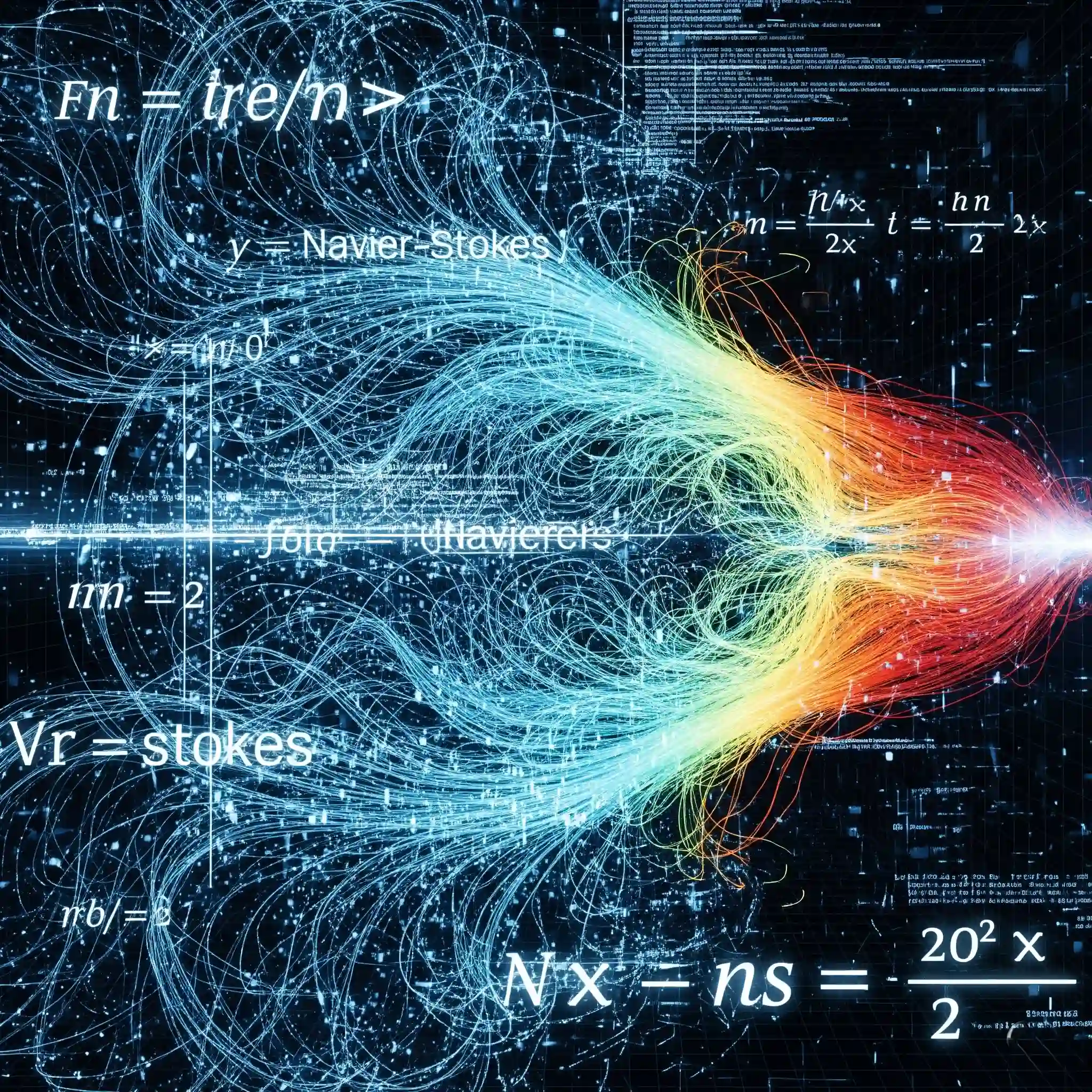
The “magic” behind CFD is a set of equations called the Navier-Stokes equations. I remember the first time I saw them in university; they looked completely impossible to solve. And by hand, they pretty much are.
Fortunately, you dont need to solve them manually. These equations are simply the fundamental rules of physics for fluid motion—governing how momentum and energy are conserved. The CFD software is the engine that does the heavy lifting, numerically solving them for each of the millions of cells in your simulation. But having a feel for what they represent is what separates a good engineer from someone who just clicks buttons. We’ve got a whole piece on The Navier-Stokes Equations for Engineers: A Practical Explanation if you want to dive deeper without the academic headache.
FVM vs. FEM: The Numerical Engines That Power CFD Simulations
You might hear terms like FVM and FEM thrown around. Think of them like choosing an engine for a car. Both get you there, but they’re built for different terrains.
The Finite Volume Method (FVM) is the workhorse for CFD. It’s exceptionally good at conserving mass, momentum, and energy, which is obviously critical for fluid flow problems. The Finite Element Method (FEM) is more of a structural analysis tool that has been adapted for fluids, often shining in multiphysics problems where you have fluid-structure interaction. For 95% of the industrial fluid dynamics work we do at CFDSource, FVM is the way to go. If you’re curious about the nitty-gritty differences, we have a guide on Finite Volume Method (FVM) vs. Finite Element Method (FEM): Which is Better for Fluid Dynamics?.
The 3 Core Stages of a CFD Simulation: The CFDSource Blueprint
Every single successful CFD project, whether it’s modeling the airflow over an airplane wing or the cooling of a tiny microchip, follows the same fundamental path. Over my 15 years in this field, I’ve seen that trying to shortcut this process is the number one reason simulations fail or produce worthless results.
We call it our blueprint, and it breaks down into three non-negotiable stages. It ensures our results are not just colorful pictures, but reliable data you can base million-dollar decisions on. We’ve written a detailed overview of the entire workflow here: The 3 Core Stages of a CFD Simulation: Pre-Processing, Solving, and Post-Processing.
Stage 1: Pre-Processing – From Messy CAD to a Simulation-Ready Model ⚙️
This is where the real work happens, and honestly, it can be 80% of the total project time. It’s guided by a simple principle: garbage in, garbage out.
It all starts with your CAD model. But here’s a painful truth: the CAD you use for manufacturing is almost never ready for simulation. It’s often full of tiny features, gaps, and surfaces that will wreck a simulation. The first step is always a meticulous cleanup process. We have a whole guide dedicated to this art form here: A Practical Guide to Geometry Preparation and Cleanup for CFD Analysis.
Once the geometry is squeaky clean, you have to chop it up into thousands, or millions, of tiny pieces called “cells.” This is meshing. The quality of this mesh will make or break your entire simulation. No exageration. A poor mesh won’t just give you a slightly inaccurate answer; it can give you a result that is 100% wrong or prevent the simulation from solving at all. Understanding things like cell quality and Y+ isn’t just academic; it’s absolutely essential for getting results you can trust. We explain it all in our guide: An Introduction to CFD Meshing: Key Concepts (Quality, Skewness, Y+) Explained.
Stage 2: Solving – Setting the Physics and Crunching the Numbers
Okay, so your mesh is perfect. Now we have to tell the computer the actual physics of the problem—the rules of the game. This is the “Solving” stage, and it’s where you define everything from the fluid properties to how you want the simulation to run. Get this part wrong, and all that beautiful pre-processing work was for nothing.
This stage breaks down into a few critical decisions:
- Defining the Boundaries: The Critical Role of Boundary Conditions. This is arguably the most critical input you will provide. You need to tell the software what’s happening at the edges of your domain—where air is flowing in, where it’s flowing out, and which surfaces are solid walls. A simple mistake here, like defining an outlet as an inlet, will produce complete nonsense. You have to be meticulous. We’ve put together a practical guide on How to Choose the Right Boundary Conditions in CFD (Inlet, Outlet, Wall, Symmetry) because we’ve seen this trip up even experienced engineers.
- Taming Chaos: A Brief Introduction to Turbulence Models. Most fluid flows in the real world are turbulent and chaotic. A computer can’t possibly simulate every single tiny swirl and eddy. So, we use “turbulence models,” which are clever mathematical approximations of that chaos. There are dozens of them, but you dont need to know them all. Often, a robust model like k-omega SST is a fantastic starting point for a huge range of industrial problems. For a gentler introduction, check out our Understanding Turbulence Models: A Beginner’s Guide to RANS, k-epsilon, and k-omega SST.
The Finish Line: What is Convergence and How Do We Achieve It? You hit “run” and the solver starts iterating, trying to find a stable solution. The goal is “convergence,” which basically means the simulation has found a steady answer and the errors are acceptably low. When a simulation doesn’t converge, it’s incredibly frustrating. The numbers just bounce around forever. Monitoring this process is key to knowing whether your results are trustworthy or just numerical noise. We cover this common headache in our simple guide on What is Convergence in CFD? A Simple Guide on How to Monitor and Achieve It.
Stage 3: Post-Processing – From Raw Data to Actionable Engineering Insights
After hours (or days!) of your workstation sounding like a jet engine, the solver finally finishes. You have gigabytes of raw data. Now what? This is post-processing—the part where we turn all that data into answers. 📈
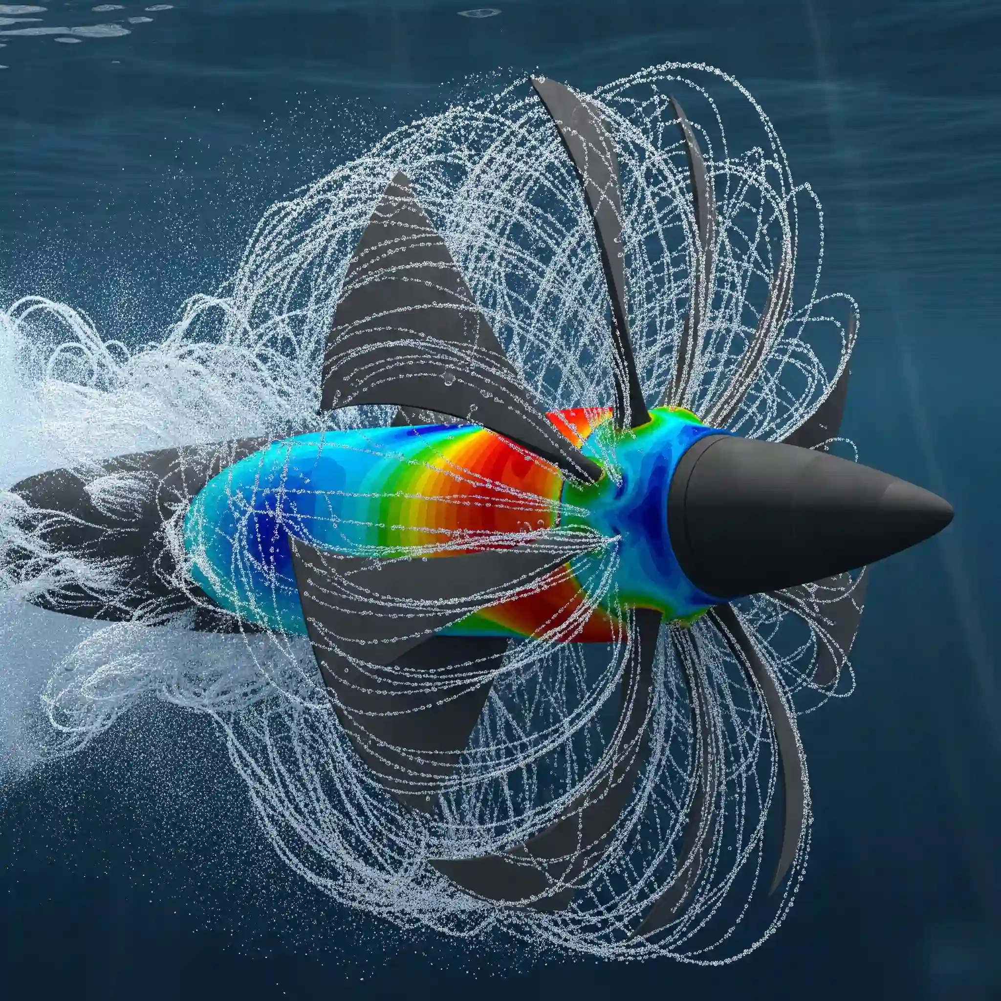
This isn’t just about making pretty, colorful pictures for a PowerPoint presentation. It’s about interrogating the results. We create plots, contour maps, and vector fields to ask critical questions: Where is the flow separating? Why is that specific component overheating? How much pressure drop are we getting? This is where the real value of Computational Fluid Dynamics is unlocked, turning simulation into insight. We have a beginner’s guide on A Beginner’s Guide to Post-Processing: How to Visualize and Interpret CFD Results that shows our process.
Real-World Impact: 10 Industries Being Transformed by CFD
CFD isn’t just an academic toy; it’s a core design tool that shapes the world around us, often in ways you wouldn’t expect. It’s the reason Formula 1 cars stick to the track at 200 mph, why your laptop doesn’t melt, and how we design more efficient and safer medical devices. 🏎️
From optimizing the aerodynamics of electric vehicles to ensuring proper ventilation in cleanrooms for pharmaceutical manufacturing, the applications are practically endless. We’ve seen it solve problems in nearly every sector. To get a better sense of its power, take a look at our list of 10 Real-World Applications of CFD (From Formula 1 to Medical Devices).
CFD vs. Physical Prototyping: When to Simulate and When to Build
So, does CFD mean we can just stop building physical prototypes altogether? The short answer is no. The smart answer is, it depends on what you’re trying to learn. The two methods aren’t enemies; they’re partners. We often use CFD to rapidly explore dozens of design ideas and rule out the bad ones before ever cutting a single piece of metal. This saves a massive amount of time and money.
Here’s a quick cheat sheet on how they stack up:
| Feature | CFD Simulation | Physical Prototype |
| Initial Cost | Lower (Software/Hardware/Expertise) | Higher (Materials, Manufacturing, Lab Time) |
| Turnaround Time | Fast (Hours to Days) | Slow (Weeks to Months) |
| Data Richness | Extremely High (Data for every point) | Low (Limited by sensor placement) |
| Design Changes | Very Easy and Cheap | Difficult and Expensive |
| Real-World Fidelity | An approximation of reality | It is reality |
The best approach is to use both intelligently. A detailed breakdown of this decision process can be found in our guide: CFD vs. Physical Prototyping: A Practical Guide to Choosing the Right Approach.
The Million-Dollar Question: Just How Accurate is CFD?
This is the big one. The question every client asks, and rightly so. Can we trust the results? The answer is: CFD is as accurate as the assumptions you make. It’s not a magic black box. The accuracy of your simulation is directly tied to the quality of your inputs—the geometry, the mesh, the physics models, and the boundary conditions.
I once worked on a heat exchanger project where the initial simulation was off by 30% compared to the experimental data. It was a disaster. The problem? The team had used a simplified CAD model and a coarse mesh to save time. We spent a week refining the model and the mesh, reran the simulation, and the results came back within 3% of the real-world test. That’s the difference between a useless simulation and an invaluable design tool. It’s a lesson you never forget. For a deeper dive into what influences accuracy, read our guide on How Accurate is CFD? A Guide to Understanding Assumptions, Models, and Sources of Error.
Our Commitment to Reality: The Art and Science of CFD Validation
A simulation without validation is just a colorful hypothesis. At CFDSource, we never just deliver a result; we deliver a result we can stand behind. Validation is the process of comparing your simulation data against real-world data to build confidence in the model. This is non-negotiable for any serious project.
This doesn’t always mean you need an expensive physical prototype. Sometimes, we can validate our models against established experimental data from academic papers or industry handbooks. The key is to have a benchmark, a ground truth, to prove that your simulation is correctly capturing the physics. This process is part science and part art, and it’s what separates a professional consultancy from a freelancer. We explain our method in detail here: How to Validate Your CFD Results: A Guide to Comparing Simulation with Experimental Data.
Avoiding Project Failure: The Top Beginner Mistakes in CFD (And How We Prevent Them)
Everyone makes mistakes when they’re starting out with CFD. I certainly did. The problem is that in a professional setting, these mistakes can lead to costly design flaws and project delays. After seeing hundreds of projects over the years, a few common errors pop up time and time again.
Things like choosing the wrong turbulence model for the flow type, not creating a fine enough mesh in critical areas (like near a wall), or simply messing up unit conversions. These sound simple, but they can completely invalidate your results. We built our internal workflows and checklists specifically to catch these issues before they become problems, ensuring that every project we deliver is built on a solid foundation. We’ve compiled a list of the most common pitfalls in our guide on The Top 10 Beginner Mistakes in CFD Simulations (And How to Avoid Them).
The Engineer’s Toolbox: An Overview of Leading CFD Software 🛠️
There isn’t one “best” CFD software; there’s only the best software for a specific job. Different tools have different strengths. For example, Ansys Fluent and CFX are industry powerhouses, known for their robustness and a massive suite of validated physics models. They’re our go-to for complex industrial applications.
On the other hand, OpenFOAM is an incredibly powerful open-source tool that offers unparalleled flexibility for customisation, which is perfect for academic research or very specific, niche problems. Then you have cloud-based platforms like SimScale which are making CFD more accessible than ever. Choosing the right tool requires experience. For a full comparison, check out our 2024 breakdown of The Best CFD Software in 2024: A Comparison of Ansys, OpenFOAM, Simscale, and Comsol.
Powering Your Simulations: What Goes into a Professional CFD Workstation?
CFD is hungry for computing power. Very hungry. Your standard office laptop isn’t going to cut it for any serious work. A proper CFD workstation is a specialized machine, and building one is about making smart choices.
It’s a common misconception that you need the most expensive graphics card (GPU). While GPUs are becoming more important, for most traditional CFD solvers, the most critical components are CPU cores and RAM. More cores mean you can solve your problem faster (in parallel), and more RAM means you can handle larger, more detailed meshes. Running out of RAM mid-simulation is a painful experience that grinds everything to a halt. We’ve put together our recommendations based on what we use every day in our guide on Building the Perfect CFD Workstation: A 2024 Guide to Hardware Requirements (CPU, RAM, GPU).
Your Partner in Simulation: Why Choose CFDSource for Your Engineering Challenges?
Look, you can learn to use CFD software from a tutorial, but you can’t learn experience. You can’t learn the intuition that tells you when a result looks “right” or “wrong” before you even see the validation data. That comes from years of running simulations, seeing them fail, figuring out why, and making them succeed.
Our value isn’t just in clicking the buttons in the right order. It’s in our ability to understand your engineering problem, translate it into the right mathematical model, and deliver insights that you can actually use to make a better product. We’ve been in the trenches, and we bring that practical, battle-tested expertise to every single project.
Get a Complimentary Technical Consultation for Your Project
If you have a design challenge that involves fluid flow, heat transfer, or multiphysics, let’s talk. We can help you determine if CFD is the right approach and what it would take to get you the answers you need. Reach out to our team to discuss your project’s technical specifications. We’re here to help you build better products through better physics.


