CFD Analysis of Airfoil: Are you curious about the magic behind the remarkable aerodynamics of aircraft wings and wind turbines? Welcome to the world of Computational Fluid Dynamics (CFD) analysis, a groundbreaking method that engineers and researchers use to understand and enhance airfoil performance.
Introduction to CFD Analysis
Computational Fluid Dynamics (CFD) is a powerful tool in the realm of engineering and aerodynamics, allowing us to delve into the intricacies of fluid flow and its interactions with solid surfaces. With the ever-increasing demand for more efficient and sustainable designs, CFD has become indispensable in a variety of industries, including aerospace, automotive, and energy. By utilizing advanced mathematics and computer simulations, CFD enables us to visualize and analyze the behavior of fluids like air in three dimensions.
This technology has revolutionized how we approach the design and analysis of airfoils, making it possible to optimize these shapes for superior aerodynamic performance. Whether it’s a wing of an aircraft, a blade of a wind turbine, or a car’s body, CFD is the key to unlocking the potential of these structures in the pursuit of efficiency and innovation.
Airfoils: The Basics
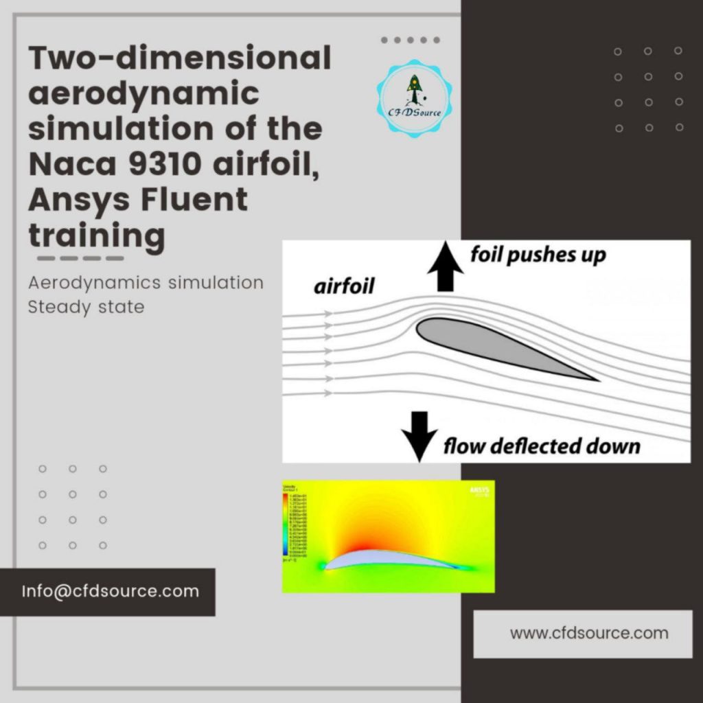
Airfoils, often referred to as wings or blades, are the fundamental components of aircraft, wind turbines, and many other aerodynamic systems. Their unique shape, characterized by a curved upper surface and a flatter lower surface, is the secret to their incredible lift and drag-reducing properties. When airfoil-shaped structures move through a fluid, such as air, they create differences in pressure between the upper and lower surfaces. This pressure differential results in lift, which is essential for keeping an aircraft aloft or driving a wind turbine. Airfoils come in various shapes and sizes, each tailored to specific applications. Understanding the basics of airfoils is the first step in comprehending how CFD can be harnessed to optimize their design and performance.
Significance of CFD in Airfoil Analysis
The significance of CFD in airfoil analysis cannot be overstated. Traditional approaches to airfoil design and analysis were based on physical wind tunnels and complex mathematical equations. While these methods were effective to a degree, they were time-consuming, expensive, and often limited in scope. CFD emerged as a game-changer, offering a virtual laboratory where engineers and researchers could explore the behavior of airfoils with remarkable precision.
It allows us to simulate and visualize how air flows over an airfoil, providing insights into lift, drag, and other aerodynamic factors. CFD has also opened the door to more innovative and efficient designs, reducing the need for costly physical testing and shortening the development cycle. Its significance extends beyond aviation; it’s instrumental in the advancement of wind turbine technology, where optimizing airfoil performance can lead to increased energy output and reduced costs.
Steps in CFD Analysis
The process of CFD analysis can be broken down into several key steps, each of which plays a critical role in ensuring accurate and insightful results. First, there’s the preprocessing stage, where the geometry of the airfoil and the surrounding domain are defined. This step involves creating a 3D model of the airfoil and setting up the simulation parameters, including the airflow conditions. Next is the simulation phase, where complex mathematical equations are solved using numerical methods. CFD software divides the airfoil’s surface into tiny cells, creating a grid or mesh.
These cells represent discrete volumes of air, and the software calculates how the air flows between them. The simulations run iteratively, with each iteration refining the results. Finally, there’s the post-processing stage, where the data generated by the simulation is analyzed and visualized. Engineers can examine the lift and drag coefficients, pressure distribution, and other aerodynamic properties to assess the airfoil’s performance. This process, though complex, is vital for achieving airfoil designs that excel in their intended applications.
Key Parameters in Airfoil CFD
Angle of Attack
One of the primary factors that significantly impacts the performance of airfoils in Computational Fluid Dynamics (CFD) analysis is the angle of attack. The angle of attack refers to the angle between the airfoil’s chord line (an imaginary line connecting the airfoil’s leading and trailing edges) and the oncoming airflow. It’s a critical parameter as it influences the lift and drag characteristics of the airfoil. At zero degrees angle of attack, the airfoil has its most neutral performance, but as the angle increases, the lift generated by the airfoil also increases.
Beyond a certain point, known as the critical angle of attack, the airflow begins to separate from the upper surface of the airfoil, leading to turbulence and reduced lift, a phenomenon called stall. Understanding the optimal angle of attack for a specific application is crucial for maximizing performance, whether it’s a fighter jet, a wind turbine blade, or a racing car wing. CFD simulations allow engineers to explore a wide range of angles of attack to identify the most efficient one for a given airfoil.
Reynolds Number
Reynolds number is another vital parameter in airfoil CFD analysis. It’s a dimensionless number that characterizes the flow of a fluid over a surface, including air over an airfoil. The Reynolds number is defined by the airfoil’s shape, size, and the speed of the airflow. In airfoil design and analysis, it’s crucial because it dictates whether the flow is laminar or turbulent. At low Reynolds numbers, the flow is typically smooth and laminar, while at high Reynolds numbers, it becomes turbulent. The transition between these two states significantly impacts an airfoil’s performance.
For example, laminar flow tends to produce less drag but might also have a lower lift coefficient, while turbulent flow can increase drag but provide higher lift. CFD simulations enable engineers to predict and analyze these transitions, helping them design airfoils that perform optimally in specific Reynolds number ranges. Whether for a sailboat sail or a helicopter rotor blade, understanding the Reynolds number is essential for efficient design.
Software and Tools for CFD Analysis
When it comes to conducting CFD analysis of airfoils, engineers and researchers have access to a variety of powerful software and tools. These tools streamline the complex process of simulating airflow over airfoils, making it more accessible and efficient. Some of the most widely used CFD software packages include ANSYS Fluent, OpenFOAM, and COMSOL Multiphysics. These packages provide a user-friendly interface for setting up simulations, defining parameters, and visualizing results. They also incorporate a wide range of numerical methods and turbulence models, making it possible to simulate real-world conditions with high accuracy. Additionally, these software tools are continuously evolving, incorporating advanced features and parallel computing capabilities, which can drastically reduce simulation time.
In addition to commercial CFD software, there are open-source alternatives like OpenFOAM. Open-source software provides flexibility and customization options, and it’s often favored in academic and research environments. It allows users to dig deep into the code, making it possible to tailor simulations to unique requirements. Many universities and research institutions leverage open-source CFD tools for cutting-edge airfoil analysis.
Meshing in CFD
Meshing is a crucial step in the CFD analysis of airfoils. It involves dividing the domain around the airfoil into a grid or mesh of smaller elements, creating a computational framework that represents the airflow. The quality of the mesh is of utmost importance, as it directly impacts the accuracy and efficiency of the simulation. Engineers must strike a balance between having a mesh fine enough to capture intricate flow details and being computationally efficient. The mesh should be denser near the airfoil’s surface where flow changes are more significant and coarser further away.
There are several techniques for generating grids, including structured, unstructured, and hybrid meshes. Structured grids are highly organized, composed of regularly shaped elements. Unstructured grids are more flexible, accommodating complex geometries, but they require more computational resources. Hybrid meshes combine elements of both structured and unstructured grids. The choice of mesh type depends on the specific airfoil and simulation requirements. Mesh quality can be assessed through parameters like aspect ratio, skewness, and orthogonal quality.
CFD software typically includes meshing tools that allow engineers to control and refine the mesh. Automating mesh generation can significantly ease the simulation setup process. The ultimate goal is to create a mesh that accurately represents the physical domain while keeping computational resources manageable.
Running the Simulation
Once the mesh is generated, it’s time to run the CFD simulation, which involves solving the complex equations that govern fluid flow. This is where the rubber meets the road, and the software crunches numbers to produce a wealth of data that characterizes the airfoil’s aerodynamic behavior. The simulation process is computationally intensive and can take hours, or even days, depending on the complexity of the analysis and available computing resources.
Simulations consider various factors, such as airfoil shape, angle of attack, airspeed, and surrounding conditions. CFD software employs numerical methods to approximate the fluid flow’s behavior, with the Navier-Stokes equations being a fundamental part of the solution. These equations describe the conservation of mass, momentum, and energy within the fluid. Numerical discretization, iterative methods, and turbulence models come into play to ensure accurate results.
Engineers can iterate through different scenarios, making adjustments to airfoil parameters, and observe how the airfoil behaves under various conditions. This iterative process is crucial for optimizing airfoil designs for specific applications. During simulation, it’s possible to calculate important aerodynamic parameters such as lift, drag, and pressure distributions, allowing engineers to make data-driven decisions for improved airfoil performance. Running the simulation is where the true power of CFD analysis shines, providing insights that drive the design and optimization of airfoils for various industries.
Post-Processing Results
After a CFD simulation of an airfoil is complete, the next critical step is post-processing. This stage involves the interpretation of the vast amount of data generated during the simulation and visualizing the results in a meaningful way. Engineers and researchers use various tools and techniques to make sense of the data and extract valuable insights.
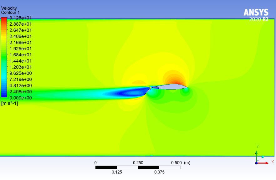
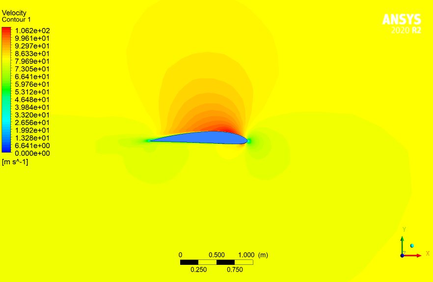
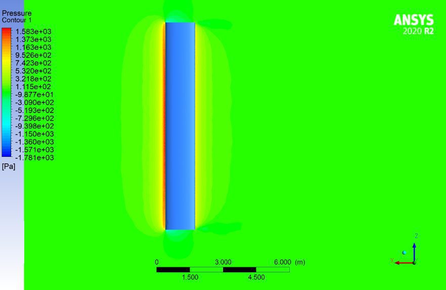
One common approach in post-processing is the creation of pressure and velocity contour plots. These plots display how pressure and velocity vary across the airfoil’s surface. Understanding pressure distributions helps in assessing lift and drag forces. Engineers can pinpoint areas of low pressure (associated with high lift) and high-pressure regions (linked to drag). Velocity contour plots provide insights into flow patterns and separation points. By analyzing these plots, engineers can fine-tune airfoil designs to minimize separation and turbulence.
Another critical aspect of post-processing is the calculation of aerodynamic coefficients, including lift and drag coefficients. These coefficients quantify an airfoil’s performance and are crucial for design and analysis. They provide a standardized way to compare different airfoil shapes and conditions. Lift and drag coefficients are related to the angle of attack, Reynolds number, and other parameters, making them valuable in optimizing airfoil designs.
Visualization is an essential part of post-processing. Engineers often use streamlines to visualize airflow over the airfoil. Streamlines are lines that show the path that air particles follow as they move around the airfoil. By examining streamlines, engineers can identify areas of flow separation, turbulence, and other aerodynamic phenomena that influence an airfoil’s performance. This visualization tool is instrumental in understanding how changes in airfoil design impact the flow pattern and can lead to more efficient designs.
In summary, post-processing is where the raw data from a CFD simulation is transformed into actionable insights. It’s the phase where engineers can assess the performance of their airfoil designs, make adjustments based on the data, and ultimately optimize their airfoils for specific applications.
Conclusion
In conclusion, Computational Fluid Dynamics (CFD) analysis of airfoils is a powerful tool that revolutionizes the design and optimization of airfoil-shaped structures. Whether applied to aircraft wings, wind turbine blades, race car spoilers, or sailboat keels, CFD allows engineers and researchers to explore the intricacies of fluid flow and aerodynamics with precision and efficiency.
Starting with an understanding of CFD’s fundamentals, we explored the basics of airfoils and their significance in various industries. We delved into the critical parameters in airfoil CFD, such as the angle of attack and the Reynolds number, and how they impact performance. We also discussed the software and tools available for conducting CFD analysis, including commercial packages and open-source options.
Meshing, the process of creating a computational grid, was examined, highlighting its importance in achieving accurate simulations. Running CFD simulations was explored, emphasizing the need for high computational resources and the significance of the simulation process in optimizing airfoil designs.
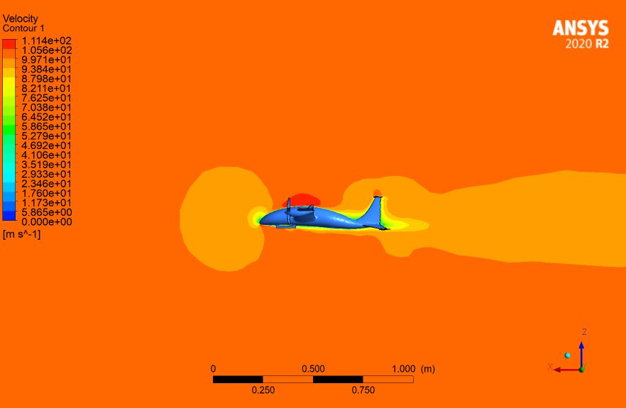
We discussed the diverse applications of airfoil CFD analysis, ranging from aircraft design and wind energy to automotive engineering, hydrodynamics, and space exploration. These applications underscore the versatile and vital role that CFD plays in numerous industries.
Challenges in CFD analysis, including accuracy, computational resources, turbulence modeling, and validation, were acknowledged. Overcoming these challenges requires ongoing research and innovation, pushing the boundaries of what CFD can achieve.
Advancements in airfoil CFD analysis were highlighted, including high-fidelity simulations, the integration of machine learning, multidisciplinary optimization, parallel computing, and the growth of open-source software. These developments are shaping the future of airfoil design, contributing to more efficient and innovative solutions.
We examined a real-world case study, showcasing how airfoil CFD analysis was applied to optimize the performance of a sailboat’s keel fin, demonstrating the practical value of this technology in competitive sailing.
CFD Analysis of Airfoil: In the ever-evolving landscape of engineering and design, airfoil CFD analysis remains a driving force, allowing us to push the boundaries of aerodynamic efficiency and innovation. With its capacity to refine airfoil shapes, improve energy output, enhance vehicle performance, and optimize hydrodynamic structures, CFD empowers engineers and researchers to reach new heights in their respective fields.


