CFD Analysis of Centrifugal Pump: Centrifugal pumps, often operating silently behind the scenes, play an indispensable role in a multitude of industries. From water treatment plants ensuring clean drinking water to massive petrochemical facilities handling volatile substances, centrifugal pumps are the unsung heroes. These remarkable machines are designed to move fluids, such as liquids and gases, by converting mechanical energy into kinetic energy, eventually into potential energy. In simple terms, they facilitate the transfer of fluids from one place to another. However, the real magic happens within their intricately designed components, such as the impeller, casing, and shaft.
The impeller, a rotating blade, is at the heart of the centrifugal pump. As it spins, it creates a whirlpool effect, drawing in fluid and expelling it with increased pressure. The casing, a stationary part surrounding the impeller, directs the flow and helps increase pressure. The shaft, which connects the impeller to the motor, keeps the impeller spinning. Together, these components choreograph a symphony of fluid movement, ensuring that water flows through our taps, fuels flow through pipelines, and chemical processes proceed as planned. This essay seeks to delve into the fascinating world of CFD (Computational Fluid Dynamics) analysis and its application in understanding and optimizing the performance of centrifugal pumps, shedding light on how these silent workhorses of industry truly operate.
Understanding CFD (Computational Fluid Dynamics)
Computational Fluid Dynamics (CFD) is the wizard’s wand that empowers engineers and researchers to peer into the mesmerizing world of fluid dynamics. It’s a numerical technique used to simulate the behavior of fluids (liquids and gases) in various engineering systems. The premise is simple: instead of conducting costly and time-consuming experiments in the real world, CFD allows us to create virtual replicas of these systems on a computer. These digital duplicates provide a dynamic canvas on which we can visualize how fluids flow, mix, react, and impact their surroundings.
CFD leverages a series of complex mathematical equations, particularly the Navier-Stokes equations, which describe the fundamental principles governing fluid motion. Solving these equations within the digital model generates a wealth of data and visualizations, allowing engineers to make informed decisions, optimize designs, and troubleshoot issues without stepping outside their offices. It’s akin to conducting a grand symphony with fluid elements, where each note represents a piece of data, and the conductor is the CFD software, directing the flow of information.
The Significance of CFD in Pump Analysis
So, what makes CFD an essential tool for analyzing centrifugal pumps? Imagine having X-ray vision into the intricate workings of a pump, being able to observe how fluids move within it, pinpoint areas of inefficiency, and optimize its performance – that’s what CFD offers. In the world of pump analysis, CFD isn’t a mere luxury; it’s a necessity. It enables engineers and researchers to understand the complexities of fluid flow, pressure changes, and energy transformations within the pump. By creating a virtual model of the centrifugal pump, complete with the impeller, casing, and shaft, CFD simulates the behavior of fluids as they pass through these components.
This simulation provides invaluable insights into the pump’s hydraulic performance. Engineers can tweak parameters, experiment with different designs, and foresee how these changes impact efficiency, all in the digital realm. Whether you’re designing a pump for a specific industrial application or trying to enhance the efficiency of an existing system, CFD is the compass guiding you through the fluid dynamics labyrinth.
Components of a Centrifugal Pump
To truly grasp the magic of CFD in pump analysis, it’s imperative to have a thorough understanding of the components that constitute a centrifugal pump. The three main components – the impeller, casing, and shaft – are akin to the stars of a well-choreographed ballet. The impeller, often the star performer, is a rotating blade with curved vanes. As it rotates at high speed, it draws in fluid from the suction port and imparts kinetic energy to it. This kinetic energy propels the fluid in a spiral path towards the outer edges of the impeller.
The casing, a stationary part encasing the impeller, plays the role of a supporting actor. It helps guide the flow of fluid and converts the kinetic energy into potential energy, increasing the pressure. Last but not least, the shaft, the unsung hero behind the scenes, connects the impeller to the motor. This connection ensures that the impeller keeps spinning, allowing the pump to continuously transfer fluid from one point to another. These components work together harmoniously to create the magic of fluid transportation that we often take for granted in our daily lives. Understanding them is the first step in unlocking the full potential of CFD in pump analysis.
Working Principle of a Centrifugal Pump
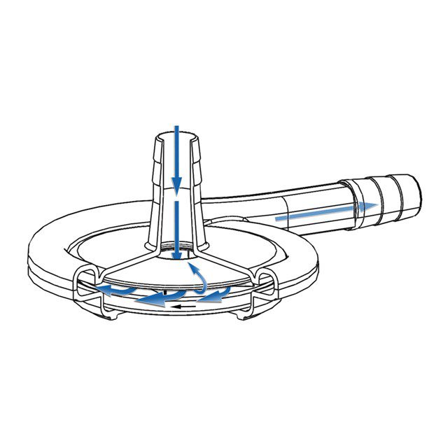
The working principle of a centrifugal pump is at the core of understanding how it accomplishes the task of fluid transportation. At its heart, this principle revolves around the conversion of mechanical energy into kinetic energy and then into potential energy. As mentioned earlier, the impeller is the key player here. When the pump is activated, the impeller rapidly rotates, creating a spinning vortex within the casing. As it whirls, the fluid enters through the suction port and is caught by the impeller’s vanes. The impeller imparts kinetic energy to the fluid, propelling it outward due to centrifugal force.
This kinetic energy increases the fluid’s velocity, creating a high-velocity flow within the pump. As the fluid moves toward the casing, it encounters the gradually expanding diameter, which serves as a diffuser. The kinetic energy is then transformed into potential energy, raising the pressure of the fluid. The now pressurized fluid exits through the discharge port and is ready for its intended purpose. In essence, a centrifugal pump is a masterful energy converter, taking mechanical energy from the motor and using it to increase the energy of the fluid, ensuring a smooth and efficient transfer.
Setting Up CFD Simulations
Now that we’ve grasped the fundamental principles behind a centrifugal pump, it’s time to explore the process of setting up CFD simulations to analyze and optimize its performance. CFD simulations are the virtual playground where engineers and researchers can experiment with different pump configurations without the need for costly physical prototypes. The process begins by creating a digital model of the centrifugal pump, including its components, geometries, and boundaries.
This model is divided into discrete elements or cells, forming the computational mesh. The mesh serves as the foundation for the simulation. It’s vital to strike a balance between mesh refinement and computational cost. A highly detailed mesh captures intricate flow behavior but requires substantial computational power. Proper mesh generation, often utilizing software tools like ANSYS or OpenFOAM, is critical for accurate results.
Mesh Generation: Laying the Foundation
Mesh generation in CFD simulations is akin to setting up the stage for a grand performance. A well-structured mesh can greatly impact the accuracy and efficiency of the simulation. Different regions of the pump, such as the impeller, casing, and volute, require varying mesh resolutions. The mesh needs to be finer in areas with complex flow patterns and higher gradients, while coarser meshes can be used in less critical regions.
Engineers must also pay attention to the type of mesh, whether structured or unstructured, to best represent the geometry of the pump. Structured meshes, with regular grids, are suitable for simpler geometries, while unstructured meshes provide more flexibility and adaptability for complex pump designs. The size and quality of the mesh can affect the simulation’s accuracy and resource requirements, making mesh generation a critical step in the CFD analysis of centrifugal pumps.

Boundary Conditions: Simulating Real-world Scenarios
For CFD simulations to be meaningful and representative of real-world scenarios, setting the right boundary conditions is paramount. In the context of a centrifugal pump, boundary conditions define how fluid interacts with the pump and its surroundings. They mimic the actual operational conditions of the pump, accounting for factors like pressure, temperature, and fluid properties. The inlet boundary conditions specify the velocity, pressure, and turbulence of the fluid entering the pump, replicating the suction process.
Meanwhile, the outlet boundary conditions define how the fluid exits the pump, including pressure or mass flow rate. Wall boundary conditions describe how the fluid interacts with the pump’s components, simulating the impact of friction and heat transfer. By accurately representing these conditions, CFD simulations can provide insights into how the pump behaves in its actual working environment, allowing engineers to fine-tune designs and optimize performance.
Solving the Navier-Stokes Equations
One of the most critical aspects of CFD analysis of centrifugal pumps is solving the Navier-Stokes equations. These equations, named after Claude-Louis Navier and George Gabriel Stokes, describe the fundamental principles that govern the motion of fluid. In the context of CFD, the Navier-Stokes equations are solved numerically to simulate fluid flow within the centrifugal pump. These equations consider the conservation of mass, momentum, and energy and are essential for understanding the intricate dynamics of the fluid as it moves through the pump.
Solving the Navier-Stokes equations reveals crucial information, such as velocity profiles, pressure distributions, and temperature variations. It’s akin to peering into the heart of the pump’s operation, offering detailed insights into the fluid’s behavior. The accuracy of these solutions is pivotal for the success of the CFD analysis and its ability to provide meaningful results for engineers and designers.
Post-processing and Visualization
The data generated through CFD simulations is rich in detail and complexity, and the process of post-processing and visualization is the key to making sense of this information. It’s where the numbers and figures are transformed into meaningful insights. Engineers and researchers use specialized software tools to visualize the flow patterns, pressure distributions, and temperature variations within the centrifugal pump. This visual representation provides an intuitive understanding of how the fluid behaves as it moves through the pump’s components.
Color-coded contour plots, streamline animations, and velocity vectors are just a few of the visualization techniques used to depict the fluid dynamics. Post-processing also involves extracting quantitative data, such as flow rates, pressure differentials, and efficiency metrics. This numerical information is crucial for evaluating the pump’s performance and can guide design improvements. In essence, post-processing and visualization turn the raw data from CFD simulations into actionable knowledge, allowing engineers to make informed decisions and optimizations.
Parameters for Performance Evaluation
In the realm of centrifugal pump analysis, performance evaluation is the ultimate goal. To achieve this, various parameters are utilized to quantify the efficiency and effectiveness of the pump. Head, which measures the pressure difference between the pump’s inlet and outlet, is a fundamental parameter. It represents the pump’s ability to push fluid through a system. Efficiency, a crucial metric, calculates how effectively the pump converts mechanical power into hydraulic power.
NPSH (Net Positive Suction Head) is a critical parameter to prevent cavitation by ensuring that the pump’s suction conditions are optimal. Flow rate, pressure, and power consumption are other essential parameters. By analyzing these metrics, engineers can gain insights into the pump’s performance and identify areas for improvement. CFD simulations offer the advantage of quickly and accurately assessing these parameters, enabling the fine-tuning of pump designs for optimal operation. Performance evaluation through CFD ensures that pumps are not just functional but operate at their peak efficiency, saving energy and resources in various industrial applications.
Conclusion: Harnessing CFD for Pump Optimization
CFD Analysis of Centrifugal Pump: In conclusion, the integration of Computational Fluid Dynamics (CFD) analysis into the realm of centrifugal pump design has ushered in a new era of precision and efficiency. By providing a digital platform for engineers to explore and understand the complex fluid dynamics within these pumps, CFD has become an invaluable tool for optimizing their performance. From understanding the fundamental principles of centrifugal pumps to setting up meticulous CFD simulations and evaluating performance parameters, CFD ensures that pumps are not just functional but operate at their peak efficiency.
It allows for innovation, design refinement, and cost savings by reducing the reliance on physical prototypes and experiments. The real-world applications span diverse industries, from aerospace and renewable energy to manufacturing and pharmaceuticals, highlighting the widespread impact of CFD analysis. While it presents challenges and requires substantial computational resources, the benefits are substantial in terms of reliability, safety, and efficiency. As technology continues to advance, CFD analysis will remain an essential tool in the ongoing quest for the optimal design and operation of centrifugal pumps, ultimately ensuring the seamless flow of fluids in our increasingly complex and interconnected world.


